AUTOMATIC HIGH BEAM SYSTEM Automatic High Beam Switch Circuit
DESCRIPTION
The main body ECU (multiplex network body ECU) detects combination switch assembly (automatic high beam main switch) signals.
The automatic high beam system can be turned on and off by operating the combination switch assembly (automatic high beam main switch).
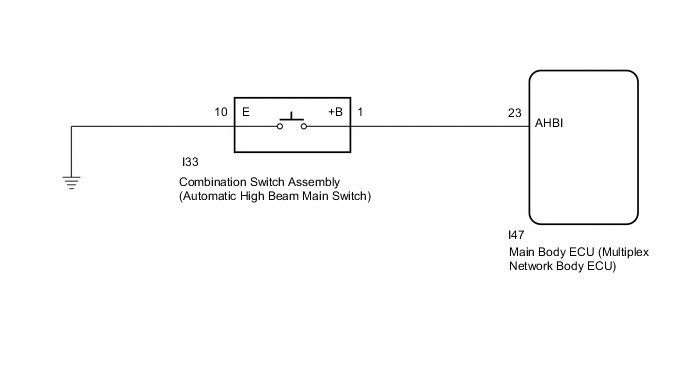
WIRING DIAGRAM
CAUTION / NOTICE / HINT
Note
-
If the main body ECU (multiplex network body ECU) is replaced, refer to Registration.
-
As the door control battery is installed between the vehicle battery and main body ECU (multiplex network body ECU), first perform the inspections in On-Vehicle Inspection to confirm that there are no malfunctions in the power source circuit for the main body ECU (multiplex network body ECU) before performing this troubleshooting procedure.*
*: w/ Door Control Battery
PROCEDURE
-
READ VALUE USING GTS (AUTO HIGH BEAM MAIN SWITCH)
-
Connect the GTS to the DLC3.
-
Turn the engine switch on (IG).
-
Turn the GTS on.
-
Enter the following menus: Body Electrical / Main Body / Data List.
-
Read the display on the GTS.
Body Electrical > Main Body > Data ListTester Display Measurement Item Range Normal Condition Diagnostic Note Auto High Beam Main Switch Combination switch assembly (automatic high beam main switch) signal ON or OFF ON: Combination switch assembly (automatic high beam main switch) pressed
OFF: Combination switch assembly (automatic high beam main switch) not pressed
-
Body Electrical > Main Body > Data ListTester Display Auto High Beam Main Switch OK Normal conditions listed above are displayed. Result Proceed to OK NG
OK 
PROCEED TO NEXT SUSPECTED AREA SHOWN IN PROBLEM SYMPTOMS TABLE Click here
NG 
-
-
INSPECT COMBINATION SWITCH ASSEMBLY
-
Remove the combination switch assembly.
-
Inspect the combination switch assembly.
Result Proceed to OK NG
NG
REPLACE COMBINATION SWITCH ASSEMBLY Click here
OK
-
-
CHECK HARNESS AND CONNECTOR (COMBINATION SWITCH ASSEMBLY - MAIN BODY ECU (MULTIPLEX NETWORK BODY ECU) AND BODY GROUND)
-
Disconnect the I33 combination switch assembly connector.
-
Disconnect the I47 main body ECU (multiplex network body ECU) connector.
-
Measure the resistance according to the value(s) in the table below.
Standard Resistance Tester Connection Condition Specified Condition I33-1 (+B) - I47-23 (AHBI) Always Below 1 Ω I33-1 (+B) - Body ground Always 10 kΩ or higher I33-10 (E) - Body ground Always Below 1 Ω Result Proceed to OK NG
OK
REPLACE MAIN BODY ECU (MULTIPLEX NETWORK BODY ECU) for LHD: REPLACE MAIN BODY ECU (MULTIPLEX NETWORK BODY ECU) Click here
REPLACE MAIN BODY ECU (MULTIPLEX NETWORK BODY ECU) for RHD: REPLACE MAIN BODY ECU (MULTIPLEX NETWORK BODY ECU) Click hereNG
REPAIR OR REPLACE HARNESS OR CONNECTOR
-