AUTOMATIC HIGH BEAM SYSTEM, Diagnostic DTC:B124A, B124C
| DTC Code | DTC Name |
|---|---|
| B124A | Automatic High Beam Mirror |
| B124C | Automatic High Beam Camera |
DESCRIPTION
This DTC is stored when the main body ECU (multiplex network body ECU) detects a malfunction in the lane departure warning camera.
| DTC No. | Detection Item | DTC Detection Condition | Trouble Area |
|---|---|---|---|
| B124A | Automatic High Beam Mirror | Malfunction in lane departure warning camera (automatic high beam sensor) |
|
| B124C | Automatic High Beam Camera | Malfunction in lane departure warning camera (automatic high beam sensor) |
|
WIRING DIAGRAM
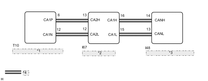
| *1 | Lane Departure Warning Camera |
| *2 | Network Gateway ECU |
| *3 | Main Body ECU (Multiplex Network Body ECU) |
| *4 | CAN Communication Line |
CAUTION / NOTICE / HINT
Note
-
Confirm that there are no CAN communication system malfunctions before performing the following inspection.
for LHD:
for RHD:
-
If the main body ECU (multiplex network body ECU) is replaced, refer to Registration.
-
As the door control battery is installed between the vehicle battery and main body ECU (multiplex network body ECU), first perform the inspections in On-Vehicle Inspection to confirm that there are no malfunctions in the power source circuit for the main body ECU (multiplex network body ECU) before performing this troubleshooting procedure.*
*: w/ Door Control Battery
-
When the lane departure warning camera is replaced with a new one, adjustment of the lane departure warning camera beam axis must be performed.
PROCEDURE
-
CHECK FOR DTC (AUTOMATIC HIGH BEAM SYSTEM)
-
Clear the DTCs.
Body Electrical > Main Body > Clear DTCs -
Check for DTCs.
Body Electrical > Main Body > Trouble CodesResult Result Proceed to DTCs B124A or B124C are not output A DTCs B124A or B124C are output B
A 
USE SIMULATION METHOD TO CHECK Click here
B
REPLACE LANE DEPARTURE WARNING CAMERA Click here
-