AUTOMATIC HEADLIGHT BEAM LEVEL CONTROL SYSTEM TERMINALS OF ECU
-
CHECK HEADLIGHT ECU SUB-ASSEMBLY LH

*A for Triple Beam Headlight - -
-
Disconnect the A19 headlight sub-assembly LH connector.
-
Measure the resistance and voltage according to the value(s) in the table below.
Terminal No. (Symbol) Wiring Color Terminal Description Condition Specified Condition A19-4 (IG) - Body ground L - Body ground Ignition power supply Engine switch off Below 1 V Engine switch on (IG) 11 to 14 V A19-13 (ECUB) - Body ground R - Body ground Power supply Engine switch off Below 1 V Engine switch on (IG) 11 to 14 V A19-12 (GND) - Body ground W-B - Body ground Ground Always Below 1 Ω -
Reconnect the A19 headlight ECU sub-assembly LH connector.
Tech Tips
Since the headlight ECU sub-assembly LH uses waterproof connectors, the voltage, resistance and waveform cannot be checked directly. The voltage, resistance and waveform are indicated for reference only.
-
Measure the voltage according to the value(s) in the table below.
Terminal No. (Symbol) Wiring Color Terminal Description Condition Specified Condition A19-16 (SBR) - A19-15 (SGR) R - P Rear height control sensor power supply Engine switch on (IG) Approximately 5 V A19-17 (SHRL) - A19-15 (SGR) L - P Rear height control sensor signal input (No passengers, no luggage, vehicle not moving) Approximately 2.5 V
(vehicle level) (value decreases as the front of the vehicle is raised)
-
-
CHECK HEADLIGHT ECU SUB-ASSEMBLY RH
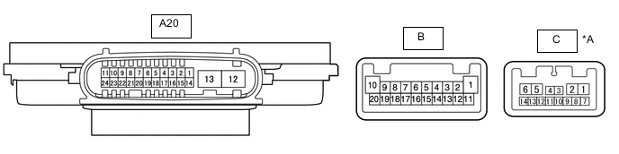
*A for Triple Beam Headlight - -
-
Disconnect the A20 headlight ECU sub-assembly RH connector.
-
Measure the resistance and voltage according to the value(s) in the table below.
Terminal No. (Symbol) Wiring Color Terminal Description Condition Specified Condition A20-4 (IG) - Body ground G - Body ground Ignition power supply Engine switch off Below 1 V Engine switch on (IG) 11 to 14 V A20-13 (ECUB) - Body ground B - Body ground Power supply Engine switch off Below 1 V Engine switch on (IG) 11 to 14 V A20-12 (GND) - Body ground W-B - Body ground Ground Always Below 1 Ω
-
-
CHECK INSTRUMENT PANEL JUNCTION BLOCK ASSEMBLY, MAIN BODY ECU (MULTIPLEX NETWORK BODY ECU)