ADAPTIVE HIGH BEAM SYSTEM, Diagnostic DTC:B2440, B2441
| DTC Code | DTC Name |
|---|---|
| B2440 | Lost Communication with AHS EDU LH Module |
| B2441 | Lost Communication with AHS EDU RH Module |
DESCRIPTION
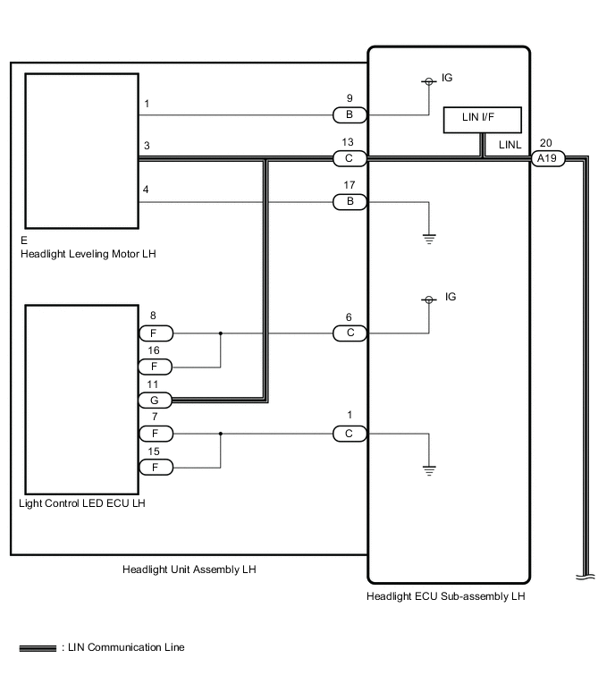
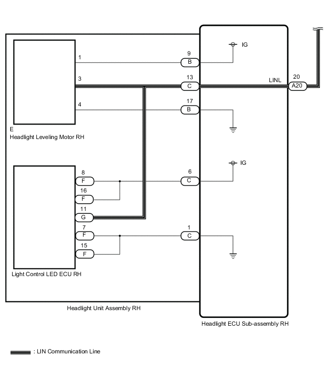
The headlight ECU sub-assembly sends operation signals to the light control LED ECU and headlight leveling motor via LIN communication.
Each part also sends its operation condition to the headlight ECU sub-assembly via LIN communication.
| DTC No. | Detection Item | DTC Detection Condition | Trouble Area |
|---|---|---|---|
| B2440 | Lost Communication with AHS EDU LH Module |
Detection Condition:
Malfunction Status:
Malfunction Duration: |
|
| B2441 | Lost Communication with AHS EDU RH Module |
Detection Condition:
Malfunction Status:
Malfunction Duration: |
|
WIRING DIAGRAM
CAUTION / NOTICE / HINT
Note
If the headlight ECU sub-assembly LH has been replaced, it is necessary to synchronize the vehicle information and initialize the headlight ECU sub-assembly LH.
PROCEDURE
-
CHECK FOR DTC
-
Clear the DTCs.
Body Electrical > AFS > Clear DTCs -
Turn the engine switch on (IG) and wait for at least 10 seconds or more.
-
Check for DTCs.
Body Electrical > AFS > Trouble CodesResult Result Proceed to DTC B2424, B2425 B2440 and B2451 are not output A DTC B2424, B2425, B2440 and B2451 are output B DTC B2424 and B2440 are output DTC B2425 and B2441 are output Only DTC B2440 is output C Only DTC B2425 is output D
A 
USE SIMULATION METHOD TO CHECK Click here
B
GO TO DTC B2424 Click here
D 
INSPECT HEADLIGHT UNIT ASSEMBLY RH Click here
C 
-
-
INSPECT HEADLIGHT UNIT ASSEMBLY LH
-
Remove the light control LED ECU LH.
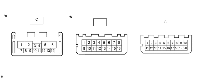
*a Component without harness connected
(Headlight ECU Sub-assembly LH)
*b Component without harness connected
(Light Control LED ECU LH)
-
Measure the resistance according to the value(s) in the table below.
Standard Resistance Tester Connection Condition Specified Condition C-6 - F-8 Always Below 1 Ω C-6 - F-16 Always Below 1 Ω C-1 - G-7 Always Below 1 Ω C-1 - G-15 Always Below 1 Ω C-13 - G-11 Always Below 1 Ω Result Proceed to OK NG
NG
REPLACE HEADLIGHT UNIT ASSEMBLY LH Click here
OK
-
-
CHECK HEADLIGHT ECU SUB-ASSEMBLY LH
-
*a Component without harness connected
(Light Control LED ECU LH)
Disconnect the light control LED ECU LH connector.
-
Reconnect the headlight ECU sub-assembly LH connectors.
-
Measure the voltage according to the value(s) in the table below.
Standard Voltage Tester Connection Switch Condition Specified Condition F-8 - F-7 Engine switch on (IG) 11 to 14 V Result Proceed to OK NG
OK
REPLACE LIGHT CONTROL LED ECU LH Click here
NG
REPLACE HEADLIGHT ECU SUB-ASSEMBLY LH Click here
-
-
INSPECT HEADLIGHT UNIT ASSEMBLY RH
-
Remove the light control LED ECU RH.
*a Component without harness connected
(Headlight ECU Sub-assembly RH)
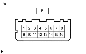
*b Component without harness connected
(Light Control LED ECU RH)
-
Measure the resistance according to the value(s) in the table below.
Standard Resistance Tester Connection Condition Specified Condition C-6 - F-8 Always Below 1 Ω C-6 - F-16 Always Below 1 Ω C-1 - G-7 Always Below 1 Ω C-1 - G-15 Always Below 1 Ω C-13 - G-11 Always Below 1 Ω Result Proceed to OK NG
NG
REPLACE HEADLIGHT UNIT ASSEMBLY RH Click here
OK
-
-
CHECK HEADLIGHT ECU SUB-ASSEMBLY RH
-
*a Component without harness connected
(Light Control LED ECU RH)
Disconnect the light control LED ECU RH connector.
-
Reconnect the headlight ECU sub-assembly RH connectors.
-
Measure the voltage according to the value(s) in the table below.
Standard Voltage Tester Connection Switch Condition Specified Condition F-8 - F-7 Engine switch on (IG) 11 to 14 V Result Proceed to OK NG
OK
REPLACE LIGHT CONTROL LED ECU RH Click here
NG
REPLACE HEADLIGHT ECU SUB-ASSEMBLY RH Click here
-