ADAPTIVE HIGH BEAM SYSTEM, Diagnostic DTC:B2490, B2491
| DTC Code | DTC Name |
|---|---|
| B2490 | Left LED Fan Circuit |
| B2491 | Right LED Fan Circuit |
DESCRIPTION
The light control LED ECU receives adaptive high beam system control signals from the headlight ECU sub-assembly via LIN communication and operates the additional fan to cool the LED in order to prevent overheating of the additional LEDs.
When the low beam headlight is illuminated, it continuously operates the additional fan.
The light control LED ECU uses pulse signals from the FANP terminal to monitor additional fan rotation signals, and when it detects a malfunction, it sends a signal to the headlight ECU sub-assembly via LIN communication.
| DTC No. | Detection Item | DTC Detection Condition | Trouble Area |
|---|---|---|---|
| B2490 | Left LED Fan Circuit |
Detection Condition:
Malfunction Status: |
|
| B2491 | Right LED Fan Circuit |
Detection Condition:
Malfunction Status: |
|
WIRING DIAGRAM
Figure 1. for LH Side:
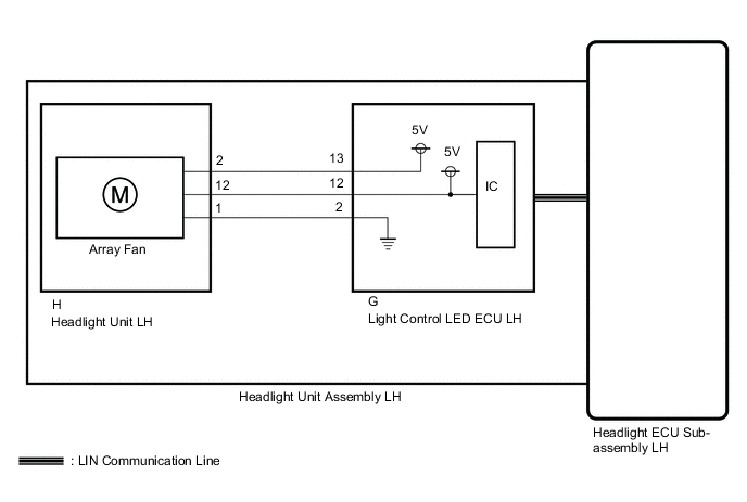
Figure 2. for RH Side:

PROCEDURE
-
CHECK FOR DTC
-
Clear the DTCs.
Body Electrical > AFS > Clear DTCs -
Turn the engine switch on (IG).
-
Operate the light control switch to turn on the low beam headlights.
-
Check for DTCs.
Body Electrical > AFS > Trouble CodesOK DTC B2490 or B2491 are not output. Result Result Proceed to OK A NG (DTC B2490 is output) B NG (DTC B2491 is output) C
A 
USE SIMULATION METHOD TO CHECK Click here
C 
INSPECT HEADLIGHT UNIT ASSEMBLY RH Click here
B 
-
-
INSPECT HEADLIGHT UNIT ASSEMBLY LH
-
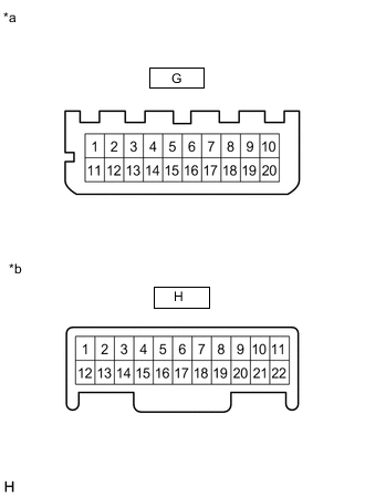
*a Component without harness connected
(Light Control LED ECU LH)
*b Component without harness connected
(Headlight Unit LH)
Remove the headlight unit LH.
-
Measure the resistance according to the value(s) in the table below.
Standard Resistance Tester Connection Condition Specified Condition G-13 - H-2 Always Below 1 Ω G-12 - H-12 Always Below 1 Ω G-2 - H-1 Always Below 1 Ω Result Proceed to OK NG
NG
REPLACE HEADLIGHT UNIT ASSEMBLY LH Click here
OK
-
-
CHECK LIGHT CONTROL LED ECU LH
-
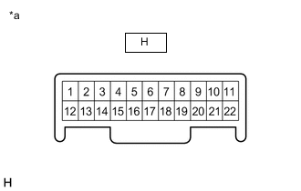
*a Component without harness connected
(Headlight Unit LH)
Remove the headlight unit LH.
-
Reconnect the headlight ECU sub-assembly LH connectors.
-
Reconnect the light control LED ECU LH connectors.
-
Measure the voltage according to the value(s) in the table below.
Standard Voltage Tester Connection Condition Specified Condition H-2 - H-1 Low beam headlights illuminated 4.75 to 5.25 V H-12 - H-1 Result Proceed to OK NG
OK
REPLACE HEADLIGHT UNIT LH Click here
NG
REPLACE LIGHT CONTROL LED ECU LH Click here
-
-
INSPECT HEADLIGHT UNIT ASSEMBLY RH
-
*a Component without harness connected
(Light Control LED ECU RH)
*b Component without harness connected
(Headlight Unit RH)
Remove the headlight unit RH.
-
Measure the resistance according to the value(s) in the table below.
Standard Resistance Tester Connection Condition Specified Condition G-13 - H-10 Always Below 1 Ω G-12 - H-22 Always Below 1 Ω G-2 - H-11 Always Below 1 Ω Result Proceed to OK NG
NG
REPLACE HEADLIGHT UNIT ASSEMBLY RH Click here
OK
-
-
CHECK LIGHT CONTROL LED ECU RH
-
*a Component without harness connected
(Headlight Unit RH)
Remove the headlight unit RH.
-
Reconnect the headlight ECU sub-assembly RH connectors.
-
Reconnect the light control LED ECU RH connectors.
-
Measure the voltage according to the value(s) in the table below.
Standard Voltage Tester Connection Condition Specified Condition H-10 - H-11 Low beam headlights illuminated 4.75 to 5.25 V H-22 - H-11 Result Proceed to OK NG
OK
REPLACE HEADLIGHT UNIT RH Click here
NG
REPLACE LIGHT CONTROL LED ECU LH Click here
-