ADAPTIVE HIGH BEAM SYSTEM TERMINALS OF ECU
-
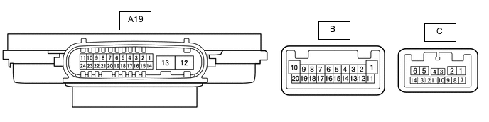
CHECK HEADLIGHT ECU SUB-ASSEMBLY LH
-
Disconnect the A19 headlight ECU sub-assembly LH connector.
-
Measure the resistance and voltage according to the value(s) in the table below.
Terminal No. (Symbol) Wiring Color Terminal Description Condition Specified Condition A19-4 (IG) - Body ground L - Body ground Ignition power supply Engine switch off Below 1 V Engine switch on (IG) 11 to 14 V A19-13 (ECUB) - Body ground R - Body ground Power supply Engine switch off Below 1 V Engine switch on (IG) 11 to 14 V A19-12 (GND) - Body ground W-B - Body ground Ground Always Below 1 Ω -
Reconnect the A19 headlight ECU sub-assembly LH connector.
Tech Tips
-
Since the A19 headlight ECU sub-assembly LH connector is a waterproof type connector, the voltage and pulses cannot be checked directly. The values listed are for reference only.
-
Since the B headlight ECU sub-assembly LH connector is connected inside the headlight assembly, the voltage and pulses cannot be checked directly. The values listed are for reference only.
-
-
Measure the voltage according to the value(s) in the table below.
Terminal No. (Symbol) Wiring Color Terminal Description Condition Specified Condition A19-6 (AZSW) - Body ground P - Body ground Combination switch assembly (adaptive high beam switch) signal Engine switch on (IG), combination switch assembly (adaptive high beam switch) off 11 to 14 V Engine switch on (IG), combination switch assembly (adaptive high beam switch) on Below 1 V
-
-
CHECK HEADLIGHT ECU SUB-ASSEMBLY RH

-
Disconnect the A20 headlight ECU sub-assembly RH connector.
-
Measure the resistance and voltage according to the value(s) in the table below.
Terminal No. (Symbol) Wiring Color Terminal Description Condition Specified Condition A20-4 (IG) - Body ground G - Body ground Ignition power supply Engine switch off Below 1 V Engine switch on (IG) 11 to 14 V A20-13 (ECUB) - Body ground B - Body ground Power supply Engine switch off Below 1 V Engine switch on (IG) 11 to 14 V A20-12 (GND) - Body ground W-B - Body ground Ground Always Below 1 Ω
-
-
CHECK INSTRUMENT PANEL JUNCTION BLOCK ASSEMBLY AND MAIN BODY ECU (MULTIPLEX NETWORK BODY ECU)
-
CHECK FORWARD RECOGNITION CAMERA
-
CHECK COMBINATION METER ASSEMBLY