LIGHTING SYSTEM Cornering Light Circuit
DESCRIPTION
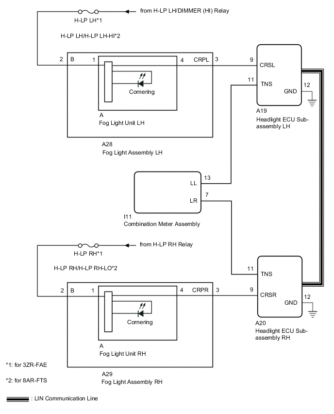
The illumination of the fog light assembly (cornering light) is controlled by the headlight ECU sub-assembly.
WIRING DIAGRAM
CAUTION / NOTICE / HINT
Note
-
The light system (exterior) uses the CAN communication system and multiplex communication system (LIN). First perform the communication function checks in "How to Proceed with Troubleshooting" to confirm that there are no communication malfunctions before proceeding with troubleshooting.
-
After the headlight ECU sub-assembly LH is replaced, vehicle information registration and initialization are necessary.
-
Check that meter/gauge system DTCs B1507 and B1508 are not output.
-
Check the fuses for circuits related to this system before performing the following inspection procedure.
PROCEDURE
-
PERFORM ACTIVE TEST USING GTS (CORNERING LIGHT)
-
Using the GTS, perform the Active Test.
-
for Triple Beam Headlight:
Body Electrical > AFS > Active TestTester Display Measurement Item Control Range Diagnostic Note Clearance Light Illuminates cornering lights OFF or ON -
Body Electrical > AFS > Active TestTester Display Clearance Light -
for Single Beam Headlight:
Body Electrical > HL AutoLeveling > Active TestTester Display Measurement Item Control Range Diagnostic Note Cornering Light Illuminates cornering lights OFF or ON -
Body Electrical > HL AutoLeveling > Active TestTester Display Cornering Light
Result Result Proceed to The Active Test is performed normally A The Active Test is not performed normally for the right side light only B The Active Test is not performed normally for the left side light only C -
A 
PROCEED TO NEXT SUSPECTED AREA SHOWN IN PROBLEM SYMPTOMS TABLE Click here
C 
CHECK HARNESS AND CONNECTOR (FOG LIGHT ASSEMBLY LH - BATTERY) Click here
B 
-
-
CHECK HARNESS AND CONNECTOR (FOG LIGHT ASSEMBLY RH - BATTERY)
-
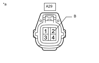
*a Front view of wire harness connector
(to Fog Light Assembly RH)
Disconnect the fog light assembly RH connector.
-
Measure the voltage according to the value(s) in the table below.
Standard Voltage Tester Connection Switch Condition Specified Condition A29-2 (B) - Body ground Engine switch on (IG) 11 to 14 V Result Proceed to OK NG
NG
REPAIR OR REPLACE HARNESS OR CONNECTOR
OK
-
-
CHECK HARNESS AND CONNECTOR (HEADLIGHT ECU SUB-ASSEMBLY RH - FOG LIGHT ASSEMBLY RH)
-
Disconnect the A20 headlight ECU sub-assembly RH connector.
-
Disconnect the A29 fog light assembly RH connector.
-
Measure the resistance according to the value(s) in the table below.
Standard Resistance Tester Connection Condition Specified Condition A20-9 (CRSR) - A29-3 (CRPR) Always Below 1 Ω A20-9 (CRSR) or A29-3 (CRPR) - Body ground Always 10 kΩ or higher Result Proceed to OK NG
NG
REPAIR OR REPLACE HARNESS OR CONNECTOR
OK
-
-
INSPECT FOG LIGHT ASSEMBLY RH
-
Remove the fog light assembly RH.
-
Inspect the fog light assembly RH.
Result Proceed to OK NG
OK
REPLACE HEADLIGH ECU SUB-ASSEMBLY RH Click here
NG
-
-
INSPECT FOG LIGHT ASSEMBLY RH
-
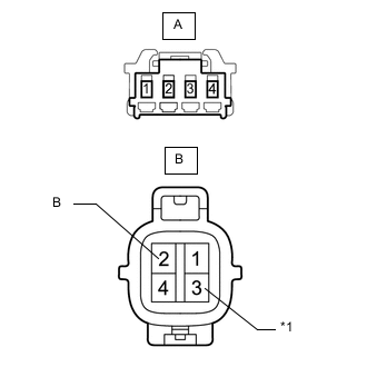
*1 CRPR Remove the fog light assembly RH.
-
Remove the fog light unit RH from the fog light assembly RH.
-
Measure the resistance according to the value(s) in the table below.
Standard Resistance Tester Connection Condition Specified Condition A-1 - B-2 (B) Always Below 1 Ω A-4 - B-3 (CRPR) Always 10 kΩ or higher Result Proceed to OK NG
OK
REPLACE FOG LIGHT UNIT RH Click here
NG
REPLACE FOG LIGHT ASSEMBLY RH Click here
-
-
CHECK HARNESS AND CONNECTOR (FOG LIGHT ASSEMBLY LH - BATTERY)
-

*a Front view of wire harness connector
(to Fog Light Assembly LH)
Disconnect the fog light assembly LH connector.
-
Measure the voltage according to the value(s) in the table below.
Standard Voltage Tester Connection Switch Condition Specified Condition A28-2 (B) - Body ground Engine switch on (IG) 11 to 14 V Result Proceed to OK NG
NG
REPAIR OR REPLACE HARNESS OR CONNECTOR
OK
-
-
CHECK HARNESS AND CONNECTOR (HEADLIGHT ECU SUB-ASSEMBLY LH - FOG LIGHT ASSEMBLY LH)
-
Disconnect the A19 headlight ECU sub-assembly LH connector.
-
Disconnect the A28 fog light assembly LH connector.
-
Measure the resistance according to the value(s) in the table below.
Standard Resistance Tester Connection Condition Specified Condition A19-9 (CRSL) - A28-3 (CRPL) Always Below 1 Ω A19-9 (CRSL) or A28-3 (CRPL) - Body ground Always 10 kΩ or higher Result Proceed to OK NG
NG
REPAIR OR REPLACE HARNESS OR CONNECTOR
OK
-
-
INSPECT FOG LIGHT ASSEMBLY LH
-
Remove the fog light assembly LH.
-
Inspect the fog light assembly LH.
Result Proceed to OK NG
OK
REPLACE HEADLIGH ECU SUB-ASSEMBLY LH Click here
NG
-
-
INSPECT FOG LIGHT ASSEMBLY LH
-

*1 CRPL Remove the fog light assembly LH.
-
Remove the fog light unit LH from the fog light assembly LH.
-
Measure the resistance according to the value(s) in the table below.
Standard Resistance Tester Connection Condition Specified Condition A-1 - B-2 (B) Always Below 1 Ω A-4 - B-3 (CRPL) Always 10 kΩ or higher Result Proceed to OK NG
OK
REPLACE FOG LIGHT UNIT LH Click here
NG
REPLACE FOG LIGHT ASSEMBLY LH Click here
-