WIPER AND WASHER SYSTEM Headlight Cleaner Motor and Relay Circuit
DESCRIPTION
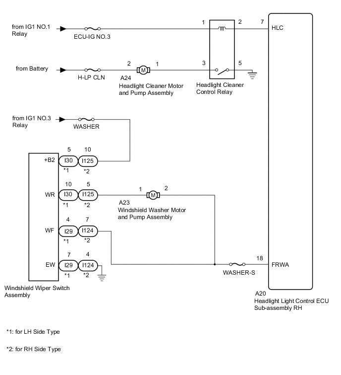
The headlight light control ECU sub-assembly RH controls the headlight cleaner motor and pump assembly.
WIRING DIAGRAM
CAUTION / NOTICE / HINT
Note
-
First check that the front washer operates normally.
-
Inspect the fuses and relays for circuits related to this system before performing the following inspection procedure.
PROCEDURE
-
READ VALUE USING GTS
-
Read the Data List according to the display on the GTS.
Body Electrical > HL AutoLeveling > Data ListTester Display Measurement Item Range Normal Condition Diagnostic Note Front Window Washer Switch Washer switch condition ON/OFF ON: Windshield wiper switch assembly (front washer switch) on
OFF: Windshield wiper switch assembly (front washer switch) off
-
Body Electrical > HL AutoLeveling > Data ListTester Display Front Window Washer Switch OK On the GTS screen, ON or OFF is displayed accordingly. Result Proceed to OK NG
NG 
CHECK HARNESS AND CONNECTOR (HEADLIGHT LIGHT CONTROL ECU SUB-ASSEMBLY RH - WINDSHIELD WIPER SWITCH ASSEMBLY) Click here
OK 
-
-
INSPECT HEADLIGHT CLEANER CONTROL RELAY
-
Remove the headlight cleaner control relay from the No. 2 engine room relay block assembly.
-
Inspect the headlight cleaner control relay.
Result Proceed to OK NG
NG 
REPLACE HEADLIGHT CLEANER CONTROL RELAY
OK
-
-
CHECK HARNESS AND CONNECTOR (HEADLIGHT CLEANER CONTROL RELAY - BATTERY)
-
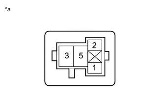
*a Front view of wire harness connector
(to Headlight Cleaner Control Relay)
Remove the headlight cleaner control relay from the No. 2 engine room relay block assembly.
-
Measure the voltage according to the value(s) in the table below.
Standard Voltage Tester Connection Switch Condition Specified Condition Headlight cleaner control relay terminal 1 - Body ground Engine switch on (IG) 11 to 14 V Result Proceed to OK NG
NG
REPAIR OR REPLACE HARNESS OR CONNECTOR
OK
-
-
CHECK HARNESS AND CONNECTOR (HEADLIGHT CLEANER MOTOR AND PUMP ASSEMBLY CIRCUIT)
-
*a Front view of wire harness connector
(to Headlight Cleaner Control Relay)
Remove the headlight cleaner control relay from the No. 2 engine room relay block assembly.
-
Using a service wire, connect terminal 3 and body ground.
Note
Do not forcibly insert the service wire into the terminals of the connector when connecting a service wire.
-
Check the headlight cleaner motor and pump assembly operate.
OK Headlight cleaner motor and pump assembly operate. Result Proceed to OK NG
NG
CHECK HARNESS AND CONNECTOR (HEADLIGHT CLEANER MOTOR AND PUMP ASSEMBLY - BATTERY) Click here
OK
-
-
CHECK HARNESS AND CONNECTOR (HEADLIGHT CLEANER CONTROL RELAY - BODY GROUND)
-
*a Front view of wire harness connector
(to Headlight Cleaner Control Relay)
Remove the headlight cleaner control relay from the No. 2 engine room relay block assembly.
-
Measure the resistance according to the value(s) in the table below.
Standard Resistance Tester Connection Condition Specified Condition Headlight cleaner control relay terminal 5 - Body ground Always Below 1 Ω Result Proceed to OK NG
NG
REPAIR OR REPLACE HARNESS OR CONNECTOR
OK
-
-
CHECK HARNESS AND CONNECTOR (HEADLIGHT CLEANER CONTROL RELAY - HEADLIGHT LIGHT CONTROL ECU SUB-ASSEMBLY RH)
-
Remove the headlight cleaner control relay from the No. 2 engine room relay block assembly.
-
Disconnect the A20 headlight light control ECU sub-assembly RH connector.
-
Measure the resistance according to the value(s) in the table below.
Standard Resistance Tester Connection Condition Specified Condition Headlight cleaner control relay terminal 2 - A20-7 (HLC) Always Below 1 Ω Headlight cleaner control relay terminal 2 or A20-7 (HLC) - Body ground Always 10 kΩ or higher Result Proceed to OK NG
OK
REPLACE HEADLIGHT LIGHT CONTROL ECU SUB-ASSEMBLY RH Click here
NG
REPAIR OR REPLACE HARNESS OR CONNECTOR
-
-
CHECK HARNESS AND CONNECTOR (HEADLIGHT LIGHT CONTROL ECU SUB-ASSEMBLY RH - WINDSHIELD WIPER SWITCH ASSEMBLY)
-
Disconnect the A20 headlight light control ECU sub-assembly RH connector.
-
Disconnect the I29*1 or I124*2 windshield wiper switch assembly connector.
-
*1: for LH Side Type
-
*2: for RH Side Type
-
-
Measure the resistance according to the value(s) in the table below.
Standard Resistance for LH Side Type Tester Connection Condition Specified Condition A20-18 (FRWA) - I29-4 (WF) Always Below 1 Ω A20-18 (FRWA) or I29-4 (WF) - Body ground Always 10 kΩ or higher for RH Side Type Tester Connection Condition Specified Condition A20-18 (FRWA) - I124-7 (WF) Always Below 1 Ω A20-18 (FRWA) or I124-7 (WF) - Body ground Always 10 kΩ or higher Result Proceed to OK NG
OK
REPLACE HEADLIGHT LIGHT CONTROL ECU SUB-ASSEMBLY RH Click here
NG
REPAIR OR REPLACE HARNESS OR CONNECTOR
-
-
CHECK HARNESS AND CONNECTOR (HEADLIGHT CLEANER MOTOR AND PUMP ASSEMBLY - BATTERY)
-
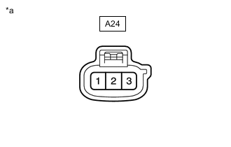
*a Front view of wire harness connector
(to Headlight Cleaner Motor and Pump Assembly)
Disconnect the headlight cleaner motor and pump assembly connector.
-
Measure the voltage according to the value(s) in the table below.
Standard Voltage Tester Connection Condition Specified Condition A24-2 - Body ground Always 11 to 14 V Result Proceed to OK NG
NG
REPAIR OR REPLACE HARNESS OR CONNECTOR
OK
-
-
INSPECT HEADLIGHT CLEANER MOTOR AND PUMP ASSEMBLY
-
Disconnect the headlight cleaner motor and pump assembly connector.
-
Inspect the headlight cleaner motor and pump assembly.
Result Proceed to OK NG
NG
REPLACE HEADLIGHT CLEANER MOTOR AND PUMP ASSEMBLY Click here
OK
-
-
CHECK HARNESS AND CONNECTOR (HEADLIGHT CLEANER MOTOR AND PUMP ASSEMBLY - HEADLIGHT CLEANER CONTROL RELAY)
-
Disconnect the A24 headlight cleaner motor and pump assembly connector.
-
Remove the headlight cleaner control relay from the No. 2 engine room relay block assembly.
-
Measure the resistance according to the value(s) in the table below.
Standard Resistance Tester Connection Condition Specified Condition A24-1 - Headlight cleaner control relay terminal 3 Always Below 1 Ω A24-1 or headlight cleaner control relay terminal 3 Always 10 kΩ or higher Result Proceed to OK NG
OK
USE SIMULATION METHOD TO CHECK Click here
NG
REPAIR OR REPLACE HARNESS OR CONNECTOR
-