WIPER AND WASHER SYSTEM TERMINALS OF ECU
-
CHECK WINDSHIELD WIPER RELAY ASSEMBLY (w/ Rain Sensor)
-
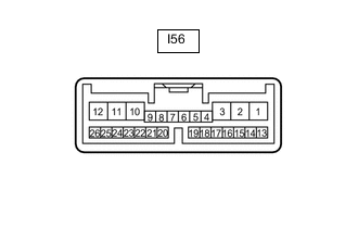
Disconnect the I56 windshield wiper relay assembly connector.
-
Measure the voltage and resistance according to the value(s) in the table below.
Tech Tips
Measure the values on the wire harness side with the connector disconnected.
Terminal No. (Symbol) Wiring Color Terminal Description Condition Specified Condition I56-2 (IG) - Body ground L - Body ground IG power supply Engine switch on (IG) 11 to 14 V Engine switch off Below 1 V I56-8 (VR2) - I56-21 (VR1) Y - W Adjusting volume circuit Windshield wiper switch assembly adjusting ring changed 0 to 231 Ω I56-12 (E) - Body ground W-B - Body ground Body ground Always Below 1 Ω I56-16 (WIG) - Body ground L - Body ground IG power supply Engine switch on (IG) 11 to 14 V Engine switch off Below 1 V -
Reconnect the I56 windshield wiper relay assembly connector.
-
Measure the voltage according to the value(s) in the table below.
Terminal No. (Symbol) Wiring Color Terminal Description Condition Specified Condition I56-1 (+SM) - Body ground G - Body ground Front wiper motor operation signal Front wiper motor in low or high operation 11 to 14 V Front wiper motor not operating Below 1 V I56-3 (C1) - I56-5 (C0) GR - L Front wiper switch AUTO position signal Engine switch on (IG), windshield wiper switch assembly in AUTO position Below 1 V Engine switch on (IG), windshield wiper switch assembly in not AUTO position 11 to 14 V I56-10 (+1) - Body ground G - Body ground Front wiper motor low speed signal Engine switch on (IG), front wiper motor in low operation 11 to 14 V Engine switch on (IG), front wiper motor not operating Below 1 V I56-11 (+2) - Body ground R - Body ground Front wiper motor high speed signal Engine switch on (IG), front wiper motor in high operation 11 to 14 V Engine switch on (IG), front wiper motor not operating Below 1 V I56-14 (MPX1) - Body ground V - Body ground LIN communication signal Engine switch on (IG) Pulse generation Engine switch off Below 1 V I56-24 (SPD) - Body ground B - Body ground Vehicle speed signal Driving at approximately 20 km/h (12 mph) Pulse generation (See waveform 1) I56-25 (W) - Body ground LA-L - Body ground Front washer motor signal Engine switch on (IG), front washer switch off 11 to 14 V Engine switch on (IG), front washer switch on Below 1 V
-
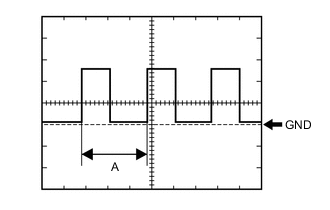
Waveform 1 (Reference):
Item Condition Tester Connection I56-24 (SPD) - Body ground Tool Setting 5 V/DIV., 20 ms./DIV. Vehicle Condition Driving at approximately 20 km/h (12 mph) Tech Tips
When the system is functioning normally, one wheel revolution generates 4 pulses. As the vehicle speed increases, the width indicated by A in the illustration narrows.
-
-
-
CHECK RAIN SENSOR (w/ Rain Sensor)
-
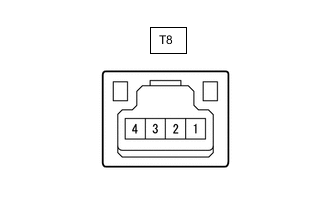
Disconnect the T8 rain sensor connector.
-
Measure the resistance and voltage according to the value(s) in the table below.
Tech Tips
Measure the values on the wire harness side with the connector disconnected.
Terminal No. (Symbol) Wiring Color Terminal Description Condition Specified Condition T8-4 (SIG) - Body ground GR - Body ground IG power supply Engine switch on (IG) 11 to 14 V Engine switch off Below 1 V T8-2 (ES) - Body ground W - Body ground Body ground Always Below 1 Ω -
Reconnect the T8 rain sensor connector.
-
Measure the voltage and waveform according to the value(s) in the table below.
Terminal No. (Symbol) Wiring Color Terminal Description Condition Specified Condition T8-1 (MPX) - Body ground V - Body ground LIN communication signal Engine switch on (IG) Pulse generation Engine switch off Below 1 V
-
-
CHECK COMBINATION METER ASSEMBLY
-
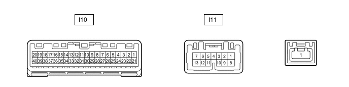
Disconnect the I10 combination meter assembly connector.
-
Measure the voltage and resistance according to the value(s) in the table below.
Tech Tips
Measure the values on the wire harness side with the connector disconnected.
Terminal No. (Symbol) Wiring Color Terminal Description Condition Specified Condition I10-22 (B) - Body ground Y - Body ground Battery power supply Always 11 to 14 V I10-21 (IG+) - Body ground B - Body ground IG power supply Engine switch on (IG) 10.5 to 16 V*1 11 to 14 V*2 Engine switch off Below 1 V I10-31 (ES) - Body ground W-B - Body ground Body ground Always Below 1 Ω *1: w/ Stop and Start System
*2: w/o Stop and Start System
-
Reconnect the I10 combination meter assembly connector.
-
Measure the voltage according to the value(s) in the table below.
Terminal No. (Symbol) Wiring Color Terminal Description Condition Specified Condition I10-16 (WLVL)* - Body ground LG - Body ground Washer fluid level signal Engine switch on (IG), washer fluid level not low 11 to 14 V Engine switch on (IG), washer fluid level low Below 1 V *: w/ Washer Level Warning System
-
Measure the waveform according to the value(s) in the table below.
Terminal No. (Symbol) Wiring Color Terminal Description Condition Specified Condition I10-19 (+S) - Body ground V - Body ground Speed signal for other system (Output) Driving at approximately 20 km/h (12 mph) Pulse generation (See waveform 1)
-
Waveform 1 (Reference):
Item Condition Tester Connection I10-19 (+S) - Body ground Tool Setting 5 V/DIV., 20 ms./DIV. Vehicle Condition Driving at approximately 20 km/h (12 mph) Tech Tips
When the system is functioning normally, one wheel revolution generates 4 pulses. As the vehicle speed increases, the width indicated by A in the illustration narrows.
-
-
-
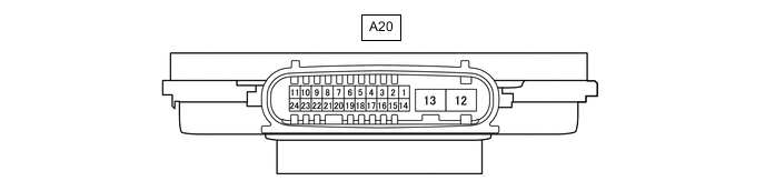
HEADLIGHT ECU SUB-ASSEMBLY RH (w/ Headlight Cleaner System)
-
Disconnect the A20 headlight ECU sub-assembly RH connector.
-
Measure the resistance and voltage according to the value(s) in the table below.
Tech Tips
Measure the values on the wire harness side with the connector disconnected.
Terminal No. (Symbol) Wiring Color Terminal Description Condition Specified Condition A20-4 (IG) - Body ground G - Body ground IG power supply Engine switch off Below 1 V Engine switch on (IG) 11 to 14 V A20-12 (GND) - Body ground W-B - Body ground Body ground Always Below 1 Ω -
Reconnect the A20 headlight ECU sub-assembly RH connector.
-
Measure the voltage according to the value(s) in the table below.
Terminal No. (Symbol) Wiring Color Terminal Description Condition Specified Condition A20-7 (HLC) - Body ground R - Body ground Headlight cleaner motor operation signal Headlight cleaner motor not operating 11 to 14 V Headlight cleaner motor operating Below 1 V A20-18 (FRWA) - Body ground B - Body ground Front washer switch signal Engine switch on (IG), front washer switch on 11 to 14 V Engine switch on (IG), front washer switch off Below 1 V
-