MILLIMETER WAVE RADAR SENSOR ADJUSTMENT

PROCEDURE
-
ADJUST MILLIMETER WAVE RADAR SENSOR ASSEMBLY
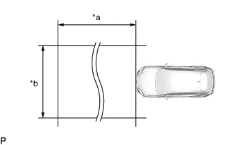
*a Approx. 10 m (32.8 ft.) *b Approx. 14 m (45.9 ft.) Note
-
Perform measurements on a level surface.
-
Make sure that no large metal objects are within a 10 m (32.8 ft.) x 14 m (45.9 ft.) area in front of the vehicle. If possible, the surrounding area should also be free of large metal objects.
-
Before adjusting the radar beam axis, prepare the vehicle as follows.
-
Remove all excess weight from the vehicle (luggage, heavy objects, etc.).
-
Check the tire pressure and adjust it if necessary.
-
Measure the vehicle height.
-
Remove the radiator support opening cover.
-
-
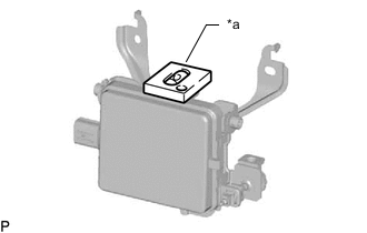
*a Level Check and adjust the vertical direction of the millimeter wave radar sensor assembly.
-
Remove dust, oil and foreign matter from the radar sensor level rack.
-
Set a level on the radar sensor level rack.
-

*a Level *b Air Bubble *c Bolt *d Vehicle Front *e Vehicle Left *f 0° *g Red Frame Check that the level's air bubble is within the red frame.
OK Level's air bubble is within red frame. If the bubble is not within the red frame, use a screwdriver to adjust the bolt until the air bubble is within the red frame.
Tech Tips
-
The adjustable range within the level's red frame is +/- 0.2°.
-
The target angle is +0.2° (upward angle of 0.2°).
Result Adjustment Direction Adjustment Procedure Adjustment Angle Upward Turn screwdriver to positive (+) side When screwdriver is turned once, adjustment changes by about 0.12° Downward Turn screwdriver to negative (-) side
-
-
-
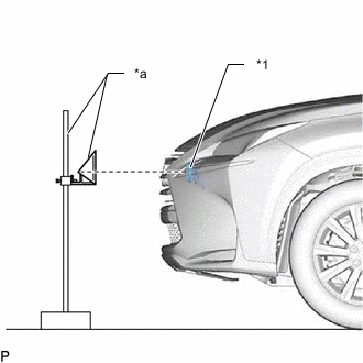
*1 Millimeter Wave Radar Sensor Assembly *a SST(Reflector) Adjust the reflector height.
-
Adjust the reflector so that the center of SST (reflector) is the same height as the millimeter wave radar sensor assembly.
- SST
- 09870-60000 ( 09870-60010 )
- 09870-60040
Tech Tips
Prepare a 10 m (32.8 ft.) string, a string with a sharp-pointed weight (plumb bob) and a 5 m (16.4 ft.) tape measure.
-
-
Place the reflector.
-
From the center of the front bumper (center of the emblem), hang a weight with a pointed tip, and mark point B on the ground.

*a String *b Weight *c Center point *d Point B -
From the center of the rear bumper (center of the emblem), hang a weight with a pointed tip, and mark point A on the ground.

*a String *b Weight *c Center point *d Point A -
Using a piece of string that uses point A as a starting point and that passes through point B, make a straight line on the ground ahead of the vehicle 5 m (16.4 ft.) or more from point B.
Tech Tips
-
Make sure to secure the string (using tape, etc.) when it is taut.
-
Lightly flick the string with your fingers several times to confirm that the string is aligned with point B.
-
-
Using a tape measure, measure a position 11 mm (0.433 in.) to the left of the 5000 mm (16.4 ft.) from the millimeter wave radar sensor. Place the reflector at that position.
Note
Perform the operation as accurately as possible.
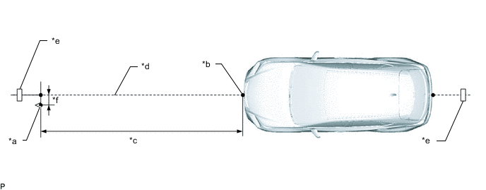
*a Reflector Placement Point *b Millimeter Wave Radar Sensor Position *c 5000 mm (16.4 ft.) *d String *e Tape *f 11 mm (0.433 in.)
-
-
Check the radar beam axis.
-
When using the GTS:
-
Connect the GTS to the DLC3.
-
Turn the engine switch on (IG).
-
Turn the GTS on and turn the cruise control main switch on.
-
Select "Connect to Vehicle".
-
Select each item on the display screen and proceed to the next screen.
-
Under "System Selection Menu", select "Radar Cruise".
-
Select "Utility" from the display screen.
-
Select "Beam Axis Adjustment" and proceed to the next screen.
-
Follow the GTS display and continue with the adjustment.
Note
-
Confirm that optical axis distance is approximately 5 m (16.4 ft.).
-
If "Error beam axis" is displayed on the screen, press the "Yes" button, and repeat again.
-
Check that there are no metal objects in the specified area in front of the vehicle (refer to the NOTICE at the beginning of this adjustment procedure).
-
Powertrain > Radar Cruise > UtilityTester Display Beam Axis Adjustment -
-
Press the "Exit" button to finish beam axis adjustment.
-
Disconnect the GTS from the DLC3.
-
-
After adjusting the radar beam axis, return the vehicle to its original condition.
-
Install the radiator support opening cover.
-
If any heavy items were removed from the vehicle, return them (luggage, heavy objects, etc.).
-
-