LANE RECOGNITION CAMERA SENSOR INSTALLATION

CAUTION / NOTICE / HINT
Note
-
When replacing the lane departure warning camera, make sure to replace it with a new one.
-
Do not touch the lens surface of the lane departure warning camera and the windshield in front of the lane departure warning camera.
-
If the lane departure warning camera is dropped, replace it with a new one.
-
If the lane departure warning camera is not installed securely, camera axis learning may not be completed correctly and the system may not operate properly. Therefore, be sure to install the camera securely.
-
If the windshield glass is replaced on a vehicle equipped with a lane departure warning camera, make sure to use a Toyota genuine part, as the lane departure warning camera may not be able to be installed due to a missing bracket or the lane departure alert system may not operate properly due to a difference in the transmissivity or ceramic line shape.
-
If the lane departure warning camera bracket is deformed or damaged, replace it together with the windshield glass.
Tech Tips
-
Use the same procedure for RHD and LHD vehicles.
-
The procedure listed below is for LHD vehicles.
PROCEDURE
-
INSTALL LANE DEPARTURE WARNING CAMERA
-
When using a new lane departure warning camera:
-
Remove the protective film.
Note
Do not touch the camera lens after removing the protective film.
-
-
Insert the 2 pins on the rear of the lane departure warning camera into the guides of the bracket.
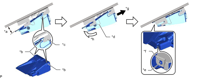
*a Approximately 10° *b Pin on rear of lane departure warning camera *c Guide *d Center bracket spring *e Pin on front of lane departure warning camera *f Hole in front side of bracket *g Press spring at center of bracket *h Push front of lane departure warning camera upwards Tech Tips
Insert the lane departure warning camera into the bracket at approximately 10°.
-
Press the spring at the center of the bracket, push the front of the lane departure warning camera upwards and insert the pin on the front of the lane departure warning camera into the hole in the front side of the bracket.
Note
Make sure that the pin on the front of the lane departure warning camera enters the hole in the front side of the bracket.
-
Connect the connector.
-
-
INSTALL NO. 1 LANE RECOGNITION COVER
-
Install the 2 clips to the No. 1 lane recognition cover.
-
Cover the bracket with the rear end of the No. 1 lane recognition cover.
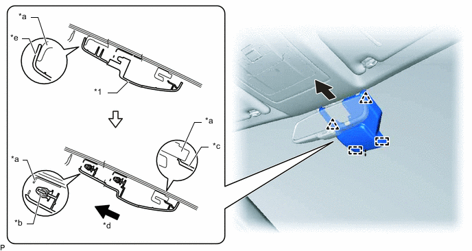
*1 No. 1 Lane Recognition Cover - - *a Bracket *b Clip *c Guide *d Slide *e Rear end of No. 1 lane recognition cover - - -
Insert the 2 guides of the No. 1 lane recognition cover into the bracket, and then while sliding the No. 1 lane recognition cover to the rear, push in the No. 1 lane recognition cover to attach the 2 rear clips to the bracket and install the cover.
-
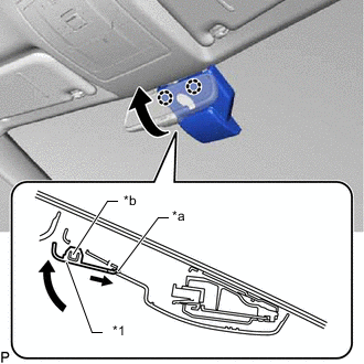
*1 No. 2 Lane Recognition Cover *a Guide *b Claw Insert the 2 guides of the No. 2 lane recognition cover into the No. 1 lane recognition cover and attach the 2 claws to install the No. 2 lane recognition cover.
-
-
ADJUST LANE DEPARTURE WARNING CAMERA