LANE DEPARTURE ALERT SYSTEM Power Source Circuit
DESCRIPTION
This circuit provides power to operate the lane departure warning camera.
WIRING DIAGRAM
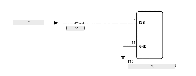
| *1 | from IG1 NO.1 Relay |
| *2 | ECU-IG NO.1 |
| *3 | Lane Departure Warning Camera |
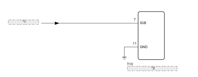
| *1 | from Engine Stop and Start ECU |
| *2 | Lane Departure Warninng Camera |
CAUTION / NOTICE / HINT
Note
w/o Stop and Start System:
Inspect the fuses for circuits related to this system before performing the following procedure.
PROCEDURE
-
CHECK HARNESS AND CONNECTOR (LANE DEPARTURE WARNING CAMERA - BATTERY AND BODY GROUND)
-
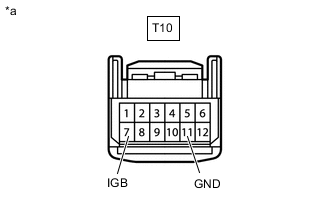
*a Front view of wire harness connector
(to Lane Departure Warning Camera)
Disconnect the lane departure warning camera connector.
-
Measure the resistance according to the value(s) in the table below.
Standard Resistance w/o Stop and Start System Tester Connection Condition Specified Condition T10-11 (GND) - Body ground Always Below 1 Ω w/ Stop and Start System Tester Connection Condition Specified Condition T10-11 (GND) - Body ground Always Below 1 Ω -
Measure the voltage according to the value(s) in the table below.
Standard Voltage w/o Stop and Start System Tester Connection Switch Condition Specified Condition T10-7 (IGB) - Body ground Engine switch on (IG) 11 to 14 V T10-7 (IGB) - Body ground Engine switch off Below 1 V w/ Stop and Start System Tester Connection Switch Condition Specified Condition T10-7 (IGB) - Body ground Engine switch on (IG) 10.5 to 16 V T10-7 (IGB) - Body ground Engine switch off Below 1 V Result Proceed to OK NG
OK 
PROCEED TO NEXT SUSPECTED AREA SHOWN IN PROBLEM SYMPTOMS TABLE Click here
NG
REPAIR OR REPLACE HARNESS OR CONNECTOR
-