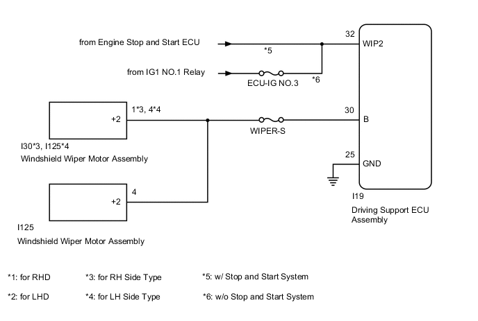
DYNAMIC RADAR CRUISE CONTROL SYSTEM Wiper Signal Circuit
DESCRIPTION
When the driving support ECU assembly detects that the wipers are operating at high speed, control of vehicle speed by the dynamic radar cruise control system is canceled.
WIRING DIAGRAM
CAUTION / NOTICE / HINT
Note
Inspect the fuses for circuits related to this system before performing the following procedure.
PROCEDURE
-
CHECK WIPER AND WASHER SYSTEM
-
Check the wiper and washer system operates normally.
OK Wiper and washer system operates normally Result Proceed to OK NG
NG 
GO TO WIPER AND WASHER SYSTEM Click here
OK 
-
-
CHECK HARNESS AND CONNECTOR (DRIVING SUPPORT ECU ASSEMBLY - BATTERY AND BODY GROUND)
-
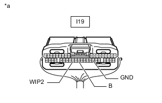
*a Rear view of wire harness connector
(to Driving Support ECU Assembly)
Disconnect the driving support ECU assembly connector.
-
Measure the voltage and resistance according to the value(s) in the table below.
Standard Voltage w/o Stop and Start System Tester Connection Switch Condition Specified Condition I19-30 (B) - Body ground Engine switch on (IG) 11 to 14 V I19-30 (B) - Body ground Engine switch off Below 1 V I19-32 (WIP2) - Body ground Engine switch on (IG), windshield wiper switch Hi 11 to 14 V w/ Stop and Start System Tester Connection Switch Condition Specified Condition I19-30 (B) - Body ground Engine switch on (IG) 10.5 to 16 V I19-30 (B) - Body ground Engine switch off Below 1 V I19-32 (WIP2) - Body ground Engine switch on (IG), windshield wiper switch Hi 11 to 14 V Standard Resistance Tester Connection Condition Specified Condition I19-25 (GND) - Body ground Always Below 1 Ω Result Proceed to OK NG
OK
PROCEED TO NEXT SUSPECTED AREA SHOWN IN PROBLEM SYMPTOMS TABLE Click here
NG
REPAIR OR REPLACE HARNESS OR CONNECTOR
-