DYNAMIC RADAR CRUISE CONTROL SYSTEM, Diagnostic DTC:P0571
| DTC Code | DTC Name |
|---|---|
| P0571 | Brake Switch "A" Circuit |
DESCRIPTION
Condition 1:
-
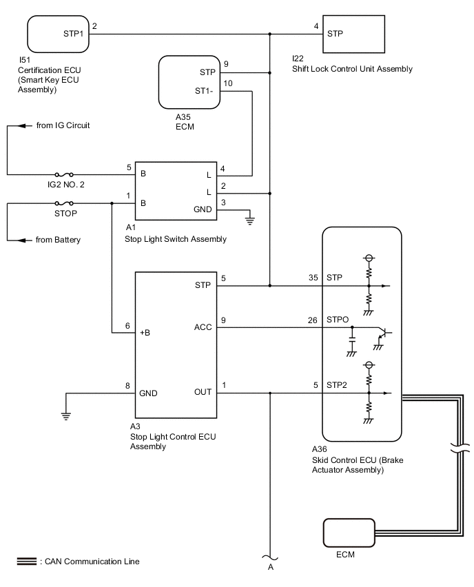
When the brakes are applied by the dynamic radar cruise control system, the skid control ECU (brake actuator assembly) operates the stop light control ECU assembly to illuminate the stop lights.
If the ECM receives a stop light control ECU assembly malfunction signal from the skid control ECU (brake actuator assembly), DTC P0571 is stored.
Condition 2:
-
When the brake pedal is depressed, the stop light switch assembly outputs a signal to the ECM. When the ECM receives the signal, it cancels control of vehicle speed by the dynamic radar cruise control system. The fail-safe function operates to enable normal operation even if there is a malfunction in the stop light signal circuit. The cancellation condition occurs when voltage is applied to terminal STP. When the brake pedal is depressed, voltage is applied to terminal STP of the ECM through the STOP fuse and the stop light switch assembly, and the ECM turns the dynamic radar cruise control system off.
| DTC No. | Detection Item | DTC Detection Condition | Trouble Area |
|---|---|---|---|
| P0571 | Brake Switch "A" Circuit | Condition 1:
Condition 2:
|
Condition 1:
Condition 2:
|
WIRING DIAGRAM
CAUTION / NOTICE / HINT
Note
-
Before replacing the certification ECU (smart key ECU assembly), refer to smart entry and start system (for Entry Function) Precaution.
-
Before replacing the ECM, refer to Service Bulletin.
-
First check the CAN communication system by following How to Proceed with Troubleshooting. After checking that there are no malfunctions in the CAN communication system, proceed with troubleshooting.
PROCEDURE
-
CHECK FOR DTCs (SFI SYSTEM)
-
Check for DTCs.
Powertrain > Engine and ECT > Trouble CodesTech Tips
Dynamic radar cruise control system DTC P0571 may be stored due to a malfunction in the SFI system. Therefore it is necessary to check for and troubleshoot SFI system DTCs first.
Result Result Proceed to SFI system DTCs are not output A SFI system DTCs are output B
B 
GO TO SFI SYSTEM Click here
A 
-
-
INSPECT TERMINAL VOLTAGE (SKID CONTROL ECU (BRAKE ACTUATOR ASSEMBLY) CONNECTOR)
-
Turn the engine switch off.
-
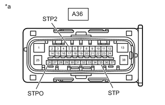
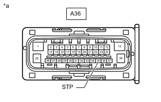
*a Front view of wire harness connector
(to Skid control ECU (Brake actuator assembly))
Disconnect the skid control ECU (brake actuator assembly) connector.
-
Measure the voltage according to the value(s) in the table below.
Standard Voltage Tester Connection Condition Specified Condition A36-35 (STP) - Body ground Brake pedal depressed 8 to 14 V Brake pedal released Below 1.5 V A36-26 (STPO) - Body ground Engine switch on (IG) 11 to 14 V A36-5 (STP2) - Body ground Brake pedal depressed 8 to 14 V Brake pedal released Below 1.5 V -
Connect the skid control ECU (brake actuator assembly) connector.
Result Result Proceed to All terminal voltage is normal A Only STP terminal voltage abnormal B Only STPO terminal voltage abnormal C Only STP2 terminal voltage abnormal D STPO terminal and STP2 terminal voltage abnormal E
B 
INSPECT TERMINAL VOLTAGE (SKID CONTROL ECU (BRAKE ACTUATOR ASSEMBLY) CONNECTOR) Click here
C
CHECK HARNESS AND CONNECTOR (SKID CONTROL ECU (BRAKE ACTUATOR ASSEMBLY) - STOP LIGHT CONTROL ECU ASSEMBLY) Click here
D
CHECK HARNESS AND CONNECTOR (SKID CONTROL ECU (BRAKE ACTUATOR ASSEMBLY) - STOP LIGHT CONTROL ECU ASSEMBLY) Click here
E
CHECK HARNESS AND CONNECTOR (SKID CONTROL ECU (BRAKE ACTUATOR ASSEMBLY) - STOP LIGHT CONTROL ECU ASSEMBLY) Click here
A
-
-
PERFORM ACTIVE TEST USING GTS (STOP LIGHT RELAY)
-
Turn the engine switch off.
-
Enter the following menus: Chassis / ABS/VSC/TRC / Active Test.
-
Perform "Active Test" according to the display on the GTS.
Chassis > ABS/VSC/TRC > Active TestTester Display Measurement Item Control Range Diagnostic Note Stop Light Relay Stop light control ECU assembly ECU (Relay) ON/OFF Stop lights come on
Vehicle condition: Vehicle stopped
Chassis > ABS/VSC/TRC > Active TestTester Display Stop Light Relay OK Stop light turns ON/OFF in response to the GTS operation Result Proceed to OK NG
NG
INSPECT SKID CONTROL ECU (BRAKE ACTUATOR ASSEMBLY) Click here
OK
-
-
CHECK FOR DTC (RADAR CRUISE 1)
-
Clear the DTCs.
Powertrain > Radar Cruise1 > Clear DTCs -
Enter the following menus: Chassis / ABS/VSC/TRC / Active Test.
-
Perform "Active Test" according to the display on the GTS.
Chassis > ABS/VSC/TRC > Active TestTester Display Measurement Item Control Range Diagnostic Note Stop Light Relay Stop light control ECU assembly ECU (Relay) ON/OFF Stop lights come on
Vehicle condition: Vehicle stopped
Chassis > ABS/VSC/TRC > Active TestTester Display Stop Light Relay -
Check for DTCs.
Powertrain > Radar Cruise1 > Trouble CodesResult Result Proceed to DTC P0571 is not output. A DTC P0571 is output. B
A
USE SIMULATION METHOD TO CHECK Click here
B
REPLACE SKID CONTROL ECU (BRAKE ACTUATOR ASSEMBLY) Click here
-
-
INSPECT SKID CONTROL ECU (BRAKE ACTUATOR ASSEMBLY)
-
Enter the following menus: Chassis / ABS/VSC/TRC / Active Test.
-
Perform "Active Test" according to the display on the GTS.
Chassis > ABS/VSC/TRC > Active TestTester Display Measurement Item Control Range Diagnostic Note Stop Light Relay Stop light control ECU assembly ECU (Relay) ON/OFF Stop lights come on
Vehicle condition: Vehicle stopped
Chassis > ABS/VSC/TRC > Active TestTester Display Stop Light Relay -
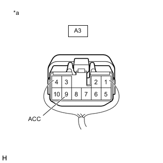
*a Component with harness connected (Stop Light Control ECU Assembly) Measure the voltage according to the value(s) in the table below.
Standard Voltage Tester Connection Condition Specified Condition A3-9 (ACC) - Body ground Active Test is ON Below 1.5 V Result Proceed to OK NG
OK
REPLACE STOP LIGHT CONTROL ECU ASSEMBLY for LHD: Click here
REPLACE STOP LIGHT CONTROL ECU ASSEMBLY for RHD: Click hereNG
REPLACE SKID CONTROL ECU (BRAKE ACTUATOR ASSEMBLY) Click here
-
-
INSPECT TERMINAL VOLTAGE (SKID CONTROL ECU (BRAKE ACTUATOR ASSEMBLY) CONNECTOR)
-
Turn the engine switch off.
-
*a Front view of wire harness connector
(to Skid control ECU (Brake actuator assembly))
Disconnect the skid control ECU (brake actuator assembly) connector.
-
Measure the voltage according to the value(s) in the table below.
Standard Voltage Tester Connection Condition Specified Condition A36-35 (STP) - Body ground Brake pedal released Below 1.5 V -
Connect the skid control ECU (brake actuator assembly) connector.
Result Proceed to OK NG
NG
INSPECT STOP LIGHT SWITCH ASSEMBLY Click here
OK
-
-
CHECK HARNESS AND CONNECTOR (SKID CONTROL ECU (BRAKE ACTUATOR ASSEMBLY) - ECM)
-
Turn the engine switch off.
-
Disconnect the A36 skid control ECU (brake actuator assembly) connector.
-
Disconnect the A35 ECM connector.
-
Measure the voltage according to the value(s) in the table below.
Standard Voltage Tester Connection Condition Specified Condition A36-35 (STP) or A35-9 (STP) - Body ground Brake pedal depressed 8 to 14 V -
Connect the A35 ECM connector.
-
Connect the A36 skid control ECU (brake actuator assembly) connector.
Result Proceed to OK NG
OK
REPLACE ECM Click here
NG
-
-
CHECK HARNESS AND CONNECTOR (SKID CONTROL ECU (BRAKE ACTUATOR ASSEMBLY) - SHIFT LOCK CONTROL UNIT ASSEMBLY)
-
Turn the engine switch off.
-
Disconnect the A36 skid control ECU (brake actuator assembly) connector.
-
Disconnect the A35 ECM connector.
-
Disconnect the I22 shift lock control unit assembly connector.
-
Measure the voltage according to the value(s) in the table below.
Standard Voltage Tester Connection Condition Specified Condition A36-35 (STP) or I22-4 (STP) - Body ground Brake pedal depressed 8 to 14 V -
Disconnect the I22 shift lock control unit assembly connector.
-
Disconnect the A35 ECM connector.
-
Disconnect the A36 skid control ECU (brake actuator assembly) connector.
Result Proceed to OK NG
OK
REPLACE SHIFT LOCK CONTROL UNIT ASSEMBLY for K114: Click here
REPLACE SHIFT LOCK CONTROL UNIT ASSEMBLY for K114F: Click hereNG
-
-
CHECK HARNESS AND CONNECTOR (SKID CONTROL ECU (BRAKE ACTUATOR ASSEMBLY) - CERTIFICATION ECU (SMART KEY ECU ASSEMBLY))
-
Turn the engine switch off.
-
Disconnect the A36 skid control ECU (brake actuator assembly) connector.
-
Disconnect the A35 ECM connector.
-
Disconnect the I22 shift lock control unit assembly connector.
-
Disconnect the I51 certification ECU (smart key ECU assembly) connector.
-
Measure the voltage according to the value(s) in the table below.
Standard Voltage Tester Connection Condition Specified Condition A36-35 (STP) or I51-2 (STP1) - Body ground Brake pedal depressed 8 to 14 V -
Connect the I51 certification ECU (smart key ECU assembly) connector.
-
Connect the I22 shift lock control unit assembly connector.
-
Connect the A35 ECM connector.
-
Connect the A36 skid control ECU (brake actuator assembly) connector.
Result Proceed to OK NG
OK
REPLACE CERTIFICATION ECU (SMART KEY ECU ASSEMBLY)
NG
CHECK WIRE HARNESS AND CONNECTOR (SKID CONTROL ECU (BRAKE ACTUATOR ASSEMBLY) - STOP LIGHT SWITCH ASSEMBLY) Click here
-
-
INSPECT STOP LIGHT SWITCH ASSEMBLY
-
Inspect the stop light switch assembly.
Result Proceed to OK NG
OK
REPAIR OR REPLACE HARNESS OR CONNECTOR
NG
REPLACE STOP LIGHT SWITCH ASSEMBLY Click here
-
-
CHECK WIRE HARNESS AND CONNECTOR (SKID CONTROL ECU (BRAKE ACTUATOR ASSEMBLY) - STOP LIGHT SWITCH ASSEMBLY)
-
Turn the engine switch off.
-
Disconnect the A36 skid control ECU (brake actuator assembly) connector.
-
Disconnect the A35 ECM connector.
-
Disconnect the I22 shift lock control unit assembly connector.
-
Disconnect the I51 certification ECU (smart key ECU assembly) connector.
-
Disconnect the A1 stop light switch assembly connector.
-
Measure the resistance according to the value(s) in the table below.
Standard Resistance Tester Connection Condition Specified Condition A1-2 (L) or A36-35 (STP) - Body ground Always 10 kΩ or higher -
Connect the A1 stop light switch assembly connector.
-
Connect the I51 certification ECU (smart key ECU assembly) connector.
-
Connect the I22 shift lock control unit assembly connector.
-
Connect the A35 ECM connector.
-
Connect the A36 skid control ECU (brake actuator assembly) connector.
Result Proceed to OK NG
NG
CHECK WIRE HARNESS AND CONNECTOR (SKID CONTROL ECU (BRAKE ACTUATOR ASSEMBLY) - STOP LIGHT CONTROL ECU ASSEMBLY) Click here
OK
-
-
INSPECT STOP LIGHT SWITCH ASSEMBLY
-
Inspect the stop light switch assembly.
Result Proceed to OK NG
OK
REPAIR OR REPLACE HARNESS OR CONNECTOR
NG
REPLACE STOP LIGHT SWITCH ASSEMBLY Click here
-
-
CHECK WIRE HARNESS AND CONNECTOR (SKID CONTROL ECU (BRAKE ACTUATOR ASSEMBLY) - STOP LIGHT CONTROL ECU ASSEMBLY)
-
Turn the engine switch off.
-
Disconnect the A36 skid control ECU (brake actuator assembly) connector.
-
Disconnect the A35 ECM connector.
-
Disconnect the I22 shift lock control unit assembly connector.
-
Disconnect the I51 certification ECU (smart key ECU assembly) connector.
-
Disconnect the A1 stop light switch assembly connector.
-
Disconnect the A3 stop light control ECU assembly connector.
-
Measure the resistance according to the value(s) in the table below.
Standard Resistance Tester Connection Condition Specified Condition A3-5 (STP) or A36-35 (STP) - Body ground Always 10 kΩ or higher -
Connect the A3 stop light control ECU assembly connector.
-
Connect the A1 stop light switch assembly connector.
-
Connect the I51 certification ECU (smart key ECU assembly) connector.
-
Connect the I22 shift lock control unit assembly connector.
-
Connect the A35 ECM connector.
-
Connect the A36 skid control ECU (brake actuator assembly) connector.
Result Proceed to OK NG
NG
REPAIR OR REPLACE HARNESS OR CONNECTOR
OK
-
-
INSPECT STOP LIGHT CONTROL ECU ASSEMBLY
-
Inspect the stop light control ECU assembly.
for LHD: Click here
for RHD: Click here
Result Proceed to OK NG
OK
REPAIR OR REPLACE HARNESS OR CONNECTOR
NG
REPLACE STOP LIGHT CONTROL ECU ASSEMBLY for LHD: Click here
REPLACE STOP LIGHT CONTROL ECU ASSEMBLY for RHD: Click here -
-
CHECK HARNESS AND CONNECTOR (SKID CONTROL ECU (BRAKE ACTUATOR ASSEMBLY) - STOP LIGHT CONTROL ECU ASSEMBLY)
-
Turn the engine switch off.
-
Disconnect the A3 stop light control ECU assembly.
-
Disconnect the A36 skid control ECU (brake actuator assembly) connector.
-
Measure the resistance according to the value(s) in the table below.
Standard Resistance Tester Connection Condition Specified Condition A36-26 (STPO) - A3-9 (ACC) Always Below 1 Ω -
Connect the A36 skid control ECU (brake actuator assembly) connector.
-
Connect the A3 stop light control ECU assembly.
Result Proceed to OK NG
NG
REPAIR OR REPLACE HARNESS OR CONNECTOR
OK
-
-
CHECK STOP LIGHT CONTROL ECU ASSEMBLY
-
Turn the engine switch off.
-
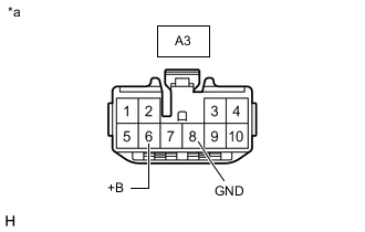
*a Front view of wire harness connector
(to Stop Light Control ECU Assembly)
Disconnect the stop light control ECU assembly connector.
-
Measure the voltage according to the value(s) in the table below.
Standard Voltage Tester Connection Condition Specified Condition A3-6 (+B) - Body ground Always 11 to 14 V -
Measure the resistance according to the value(s) in the table below.
Standard Resistance Tester Connection Condition Specified Condition A3-8 (GND) - Body ground Always Below 1 Ω -
Connect the stop light control ECU assembly connector.
Result Proceed to OK NG
OK
REPLACE STOP LIGHT CONTROL ECU ASSEMBLY for LHD: Click here
REPLACE STOP LIGHT CONTROL ECU ASSEMBLY for RHD: Click hereNG
REPAIR OR REPLACE HARNESS OR CONNECTOR
-
-
CHECK HARNESS AND CONNECTOR (SKID CONTROL ECU (BRAKE ACTUATOR ASSEMBLY) - STOP LIGHT CONTROL ECU ASSEMBLY)
-
Turn the engine switch off.
-
Disconnect the A3 stop light control ECU assembly.
-
Disconnect the skid control ECU (brake actuator assembly) connector.
-
Measure the resistance according to the value(s) in the table below.
Standard Resistance Tester Connection Condition Specified Condition A36-35 (STP) - A3-5 (STP) Always Below 1 Ω -
Connect the skid control ECU (brake actuator assembly) connector.
-
Connect the A3 stop light control ECU assembly.
Result Proceed to OK NG
NG
REPAIR OR REPLACE HARNESS OR CONNECTOR
OK
-
-
INSPECT TERMINAL VOLTAGE (SKID CONTROL ECU (BRAKE ACTUATOR ASSEMBLY) CONNECTOR)
-
Turn the engine switch off.
-
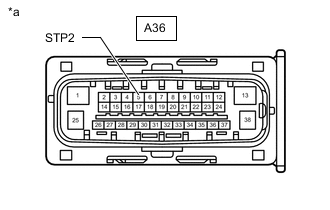
*a Front view of wire harness connector
(to Skid control ECU (Brake actuator assembly))
Disconnect the skid control ECU (brake actuator assembly) connector.
-
Measure the voltage according to the value(s) in the table below.
Standard Voltage Tester Connection Condition Specified Condition A36-5 (STP2) - Body ground Brake pedal released Below 1.5 V -
Connect the skid control ECU (brake actuator assembly) connector.
Result Proceed to OK NG
NG
CHECK HARNESS AND CONNECTOR (SKID CONTROL ECU (BRAKE ACTUATOR ASSEMBLY) - STOP LIGHT CONTROL ECU ASSEMBLY) Click here
OK
-
-
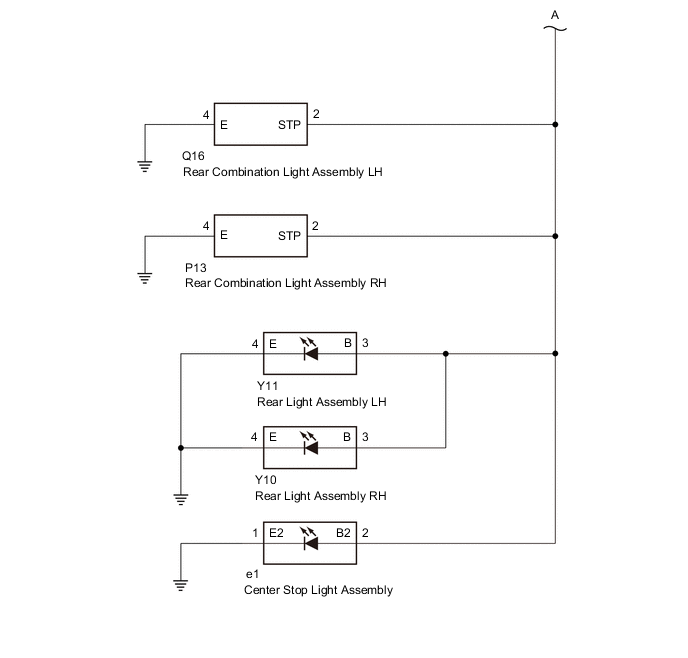
CHECK HARNESS AND CONNECTOR (SKID CONTROL ECU (BRAKE ACTUATOR ASSEMBLY) - REAR COMBINATION LIGHT ASSEMBLY LH)
-
Turn the engine switch off.
-
Disconnect the A36 skid control ECU (brake actuator assembly) connector.
-
Disconnect the Q16 rear combination light assembly LH connector.
-
Measure the voltage according to the value(s) in the table below.
Standard Voltage Tester Connection Condition Specified Condition A36-5 (STP2) or Q16-2 (STP) - Body ground Brake pedal depressed 8 to 14 V -
Connect the Q16 rear combination light assembly LH connector.
-
Connect the A36 skid control ECU (brake actuator assembly) connector.
Result Proceed to OK NG
OK
REPLACE REAR COMBINATION LIGHT ASSEMBLY LH Click here
NG
-
-
CHECK HARNESS AND CONNECTOR (SKID CONTROL ECU (BRAKE ACTUATOR ASSEMBLY) - REAR COMBINATION LIGHT ASSEMBLY RH)
-
Turn the engine switch off.
-
Disconnect the A36 skid control ECU (brake actuator assembly) connector.
-
Disconnect the Q16 rear combination light assembly LH connector.
-
Disconnect the P13 rear combination light assembly RH connector.
-
Measure the voltage according to the value(s) in the table below.
Standard Voltage Tester Connection Condition Specified Condition A36-5 (STP2) or P13-2 (STP) - Body ground Brake pedal depressed 8 to 14 V -
Connect the P13 rear combination light assembly RH connector.
-
Connect the Q16 rear combination light assembly LH connector.
-
Connect the A36 skid control ECU (brake actuator assembly) connector.
Result Proceed to OK NG
OK
REPLACE REAR COMBINATION LIGHT ASSEMBLY RH Click here
NG
-
-
CHECK HARNESS AND CONNECTOR (SKID CONTROL ECU (BRAKE ACTUATOR ASSEMBLY) - REAR LIGHT ASSEMBLY LH)
-
Turn the engine switch off.
-
Disconnect the A36 skid control ECU (brake actuator assembly) connector.
-
Disconnect the Q16 rear combination light assembly LH connector.
-
Disconnect the P13 rear combination light assembly RH connector.
-
Disconnect the Y11 rear light assembly LH connector.
-
Measure the voltage according to the value(s) in the table below.
Standard Voltage Tester Connection Condition Specified Condition A36-5 (STP2) or Y11-3 (B) - Body ground Brake pedal depressed 8 to 14 V -
Connect the Y11 rear light assembly LH connector.
-
Connect the P13 rear combination light assembly RH connector.
-
Connect the Q16 rear combination light assembly LH connector.
-
Connect the A36 skid control ECU (brake actuator assembly) connector.
Result Proceed to OK NG
OK
REPLACE REAR LIGHT ASSEMBLY LH Click here
NG
-
-
CHECK HARNESS AND CONNECTOR (SKID CONTROL ECU (BRAKE ACTUATOR ASSEMBLY) - REAR LIGHT ASSEMBLY RH)
-
Turn the engine switch off.
-
Disconnect the A36 skid control ECU (brake actuator assembly) connector.
-
Disconnect the Q16 rear combination light assembly LH connector.
-
Disconnect the P13 rear combination light assembly RH connector.
-
Disconnect the Y11 rear light assembly LH connector.
-
Disconnect the Y10 rear light assembly RH connector.
-
Measure the voltage according to the value(s) in the table below.
Standard Voltage Tester Connection Condition Specified Condition A36-5 (STP2) or Y10-3 (B) - Body ground Brake pedal depressed 8 to 14 V -
Connect the Y10 rear light assembly RH connector.
-
Connect the Y11 rear light assembly LH connector.
-
Connect the P13 rear combination light assembly RH connector.
-
Connect the Q16 rear combination light assembly LH connector.
-
Connect the A36 skid control ECU (brake actuator assembly) connector.
Result Proceed to OK NG
OK
REPLACE REAR LIGHT ASSEMBLY RH Click here
NG
-
-
CHECK HARNESS AND CONNECTOR (SKID CONTROL ECU (BRAKE ACTUATOR ASSEMBLY) - CENTER STOP LIGHT ASSEMBLY)
-
Turn the engine switch off.
-
Disconnect the A36 skid control ECU (brake actuator assembly) connector.
-
Disconnect the Q16 rear combination light assembly LH connector.
-
Disconnect the P13 rear combination light assembly RH connector.
-
Disconnect the Y11 rear light assembly LH connector.
-
Disconnect the Y10 rear light assembly RH connector.
-
Disconnect the e1 center stop light assembly connector.
-
Measure the voltage according to the value(s) in the table below.
Standard Voltage Tester Connection Condition Specified Condition A36-5 (STP2) or e1-2 (B2) - Body ground Brake pedal depressed 8 to 14 V -
Connect the e1 center stop light assembly connector.
-
Connect the Y10 rear light assembly RH connector.
-
Connect the Y11 rear light assembly LH connector.
-
Connect the P13 rear combination light assembly RH connector.
-
Connect the Q16 rear combination light assembly LH connector.
-
Connect the A36 skid control ECU (brake actuator assembly) connector.
Result Proceed to OK NG
OK
REPLACE CENTER STOP LIGHT ASSEMBLY Click here
NG
-
-
CHECK HARNESS AND CONNECTOR (SKID CONTROL ECU (BRAKE ACTUATOR ASSEMBLY) - STOP LIGHT CONTROL ECU ASSEMBLY)
-
Turn the engine switch off.
-
Disconnect the A36 skid control ECU (brake actuator assembly) connector.
-
Disconnect the Q16 rear combination light assembly LH connector.
-
Disconnect the P13 rear combination light assembly RH connector.
-
Disconnect the Y11 rear light assembly LH connector.
-
Disconnect the Y10 rear light assembly RH connector.
-
Disconnect the e1 center stop light assembly connector.
-
Disconnect the A3 stop light control ECU assembly connector.
-
Measure the resistance according to the value(s) in the table below.
Standard Resistance Tester Connection Condition Specified Condition A3-1 (OUT) - A36-5 (STP2) Always Below 1 Ω A3-1 (OUT) or A36-5 (STP2) - Body ground Always 10 kΩ or higher -
Connect the A3 stop light control ECU assembly connector.
-
Connect the e1 center stop light assembly connector.
-
Connect the Y10 rear light assembly RH connector.
-
Connect the Y11 rear light assembly LH connector.
-
Connect the P13 rear combination light assembly RH connector.
-
Connect the Q16 rear combination light assembly LH connector.
-
Connect the A36 skid control ECU (brake actuator assembly) connector.
Result Proceed to OK NG
OK
REPLACE STOP LIGHT CONTROL ECU ASSEMBLY for LHD: Click here
REPLACE STOP LIGHT CONTROL ECU ASSEMBLY for RHD: Click hereNG
REPAIR OR REPLACE HARNESS OR CONNECTOR
-
-
CHECK HARNESS AND CONNECTOR (SKID CONTROL ECU (BRAKE ACTUATOR ASSEMBLY) - STOP LIGHT CONTROL ECU ASSEMBLY)
-
Turn the engine switch off.
-
Disconnect the A36 skid control ECU (brake actuator assembly) connector.
-
Disconnect the A3 stop light control ECU assembly.
-
Measure the voltage according to the value(s) in the table below.
Standard Voltage Tester Connection Condition Specified Condition A36-5 (STP2) or A3-1 (OUT) - Body ground Brake pedal released Below 1.5 V -
Connect the A3 stop light control ECU assembly.
-
Connect the A36 skid control ECU (brake actuator assembly) connector.
Result Proceed to OK NG
OK
REPLACE STOP LIGHT CONTROL ECU ASSEMBLY for LHD: Click here
REPLACE STOP LIGHT CONTROL ECU ASSEMBLY for RHD: Click hereNG
-
-
CHECK HARNESS AND CONNECTOR (SKID CONTROL ECU (BRAKE ACTUATOR ASSEMBLY) - REAR COMBINATION LIGHT ASSEMBLY LH)
-
Turn the engine switch off.
-
Disconnect the A36 skid control ECU (brake actuator assembly) connector.
-
Disconnect the A3 stop light control ECU assembly.
-
Disconnect the Q16 rear combination light assembly LH connector.
-
Measure the voltage according to the value(s) in the table below.
Standard Voltage Tester Connection Condition Specified Condition A36-5 (STP2) or Q16-2 (STP) - Body ground Brake pedal released Below 1.5 V -
Connect the Q16 rear combination light assembly LH connector.
-
Connect the A3 stop light control ECU assembly.
-
Connect the A36 skid control ECU (brake actuator assembly) connector.
Result Proceed to OK NG
OK
REPLACE REAR COMBINATION LIGHT ASSEMBLY LH Click here
NG
-
-
CHECK HARNESS AND CONNECTOR (SKID CONTROL ECU (BRAKE ACTUATOR ASSEMBLY) - REAR COMBINATION LIGHT ASSEMBLY RH)
-
Turn the engine switch off.
-
Disconnect the A36 skid control ECU (brake actuator assembly) connector.
-
Disconnect the A3 stop light control ECU assembly.
-
Disconnect the Q16 rear combination light assembly LH connector.
-
Disconnect the P13 rear combination light assembly RH connector.
-
Measure the voltage according to the value(s) in the table below.
Standard Voltage Tester Connection Tester Connection Specified Condition A36-5 (STP2) or P13-2 (STP) - Body ground Brake pedal released Below 1.5 V -
Connect the P13 rear combination light assembly RH connector.
-
Connect the Q16 rear combination light assembly LH connector.
-
Connect the A3 stop light control ECU assembly.
-
Connect the A36 skid control ECU (brake actuator assembly) connector.
Result Proceed to OK NG
OK
REPLACE REAR COMBINATION LIGHT ASSEMBLY RH Click here
NG
-
-
CHECK HARNESS AND CONNECTOR (SKID CONTROL ECU (BRAKE ACTUATOR ASSEMBLY) - REAR LIGHT ASSEMBLY LH)
-
Turn the engine switch off.
-
Disconnect the A36 skid control ECU (brake actuator assembly) connector.
-
Disconnect the A3 stop light control ECU assembly.
-
Disconnect the Q16 rear combination light assembly LH connector.
-
Disconnect the P13 rear combination light assembly RH connector.
-
Disconnect the Y11 rear light assembly LH connector.
-
Measure the voltage according to the value(s) in the table below.
Standard Voltage Tester Connection Condition Specified Condition A36-5 (STP2) or Y11-3 (B) - Body ground Brake pedal released Below 1.5 V -
Connect the Y11 rear light assembly LH connector.
-
Connect the P13 rear combination light assembly RH connector.
-
Connect the Q16 rear combination light assembly LH connector.
-
Connect the A3 stop light control ECU assembly.
-
Connect the A36 skid control ECU (brake actuator assembly) connector.
Result Proceed to OK NG
OK
REPLACE REAR LIGHT ASSEMBLY LH Click here
NG
-
-
CHECK HARNESS AND CONNECTOR (SKID CONTROL ECU (BRAKE ACTUATOR ASSEMBLY) - REAR LIGHT ASSEMBLY RH)
-
Turn the engine switch off.
-
Disconnect the A36 skid control ECU (brake actuator assembly) connector.
-
Disconnect the A3 stop light control ECU assembly.
-
Disconnect the Q16 rear combination light assembly LH connector.
-
Disconnect the P13 rear combination light assembly RH connector.
-
Disconnect the Y11 rear light assembly LH connector.
-
Disconnect the Y10 rear light assembly RH connector.
-
Measure the voltage according to the value(s) in the table below.
Standard Voltage Tester Connection Condition Specified Condition A36-5 (STP2) or Y10-3 (B) - Body ground Brake pedal released Below 1.5 V -
Connect the Y10 rear light assembly RH connector.
-
Connect the Y11 rear light assembly LH connector.
-
Connect the P13 rear combination light assembly RH connector.
-
Connect the Q16 rear combination light assembly LH connector.
-
Connect the A3 stop light control ECU assembly.
-
Connect the A36 skid control ECU (brake actuator assembly) connector.
Result Proceed to OK NG
OK
REPLACE REAR LIGHT ASSEMBLY RH Click here
NG
-
-
CHECK HARNESS AND CONNECTOR (SKID CONTROL ECU (BRAKE ACTUATOR ASSEMBLY) - CENTER STOP LIGHT ASSEMBLY)
-
Turn the engine switch off.
-
Disconnect the A36 skid control ECU (brake actuator assembly) connector.
-
Disconnect the A3 stop light control ECU assembly.
-
Disconnect the Q16 rear combination light assembly LH connector.
-
Disconnect the P13 rear combination light assembly RH connector.
-
Disconnect the Y11 rear light assembly LH connector.
-
Disconnect the Y10 rear light assembly RH connector.
-
Disconnect the e1 center stop light assembly connector.
-
Measure the voltage according to the value(s) in the table below.
Standard Voltage Tester Connection Condition Specified Condition A36-5 (STP2) or e1-2 (B2) - Body ground Brake pedal released Below 1.5 V -
Connect the e1 center stop light assembly connector.
-
Connect the Y10 rear light assembly RH connector.
-
Connect the Y11 rear light assembly LH connector.
-
Connect the P13 rear combination light assembly RH connector.
-
Connect the Q16 rear combination light assembly LH connector.
-
Connect the A3 stop light control ECU assembly.
-
Connect the A36 skid control ECU (brake actuator assembly) connector.
Result Proceed to OK NG
OK
REPLACE CENTER STOP LIGHT ASSEMBLY Click here
NG
REPAIR OR REPLACE HARNESS OR CONNECTOR
-
-
CHECK HARNESS AND CONNECTOR (SKID CONTROL ECU (BRAKE ACTUATOR ASSEMBLY) - STOP LIGHT CONTROL ECU ASSEMBLY)
-
Turn the engine switch off.
-
Disconnect the A36 skid control ECU (brake actuator assembly) connector.
-
Disconnect the A3 stop light control ECU assembly connector.
-
Measure the resistance according to the value(s) in the table below.
Standard Resistance Tester Connection Condition Specified Condition A36-26 (STPO) or A3-9 (ACC) - Body ground Always 10 kΩ or higher -
Connect the A3 stop light control ECU assembly connector.
-
Connect the A36 skid control ECU (brake actuator assembly) connector.
Result Proceed to OK NG
OK
REPLACE STOP LIGHT CONTROL ECU ASSEMBLY for LHD: Click here
REPLACE STOP LIGHT CONTROL ECU ASSEMBLY for RHD: Click hereNG
REPAIR OR REPLACE HARNESS OR CONNECTOR
-