DYNAMIC RADAR CRUISE CONTROL SYSTEM, Diagnostic DTC:C1A4A
| DTC Code | DTC Name |
|---|---|
| C1A4A | Skid Control Buzzer Circuit |
DESCRIPTION
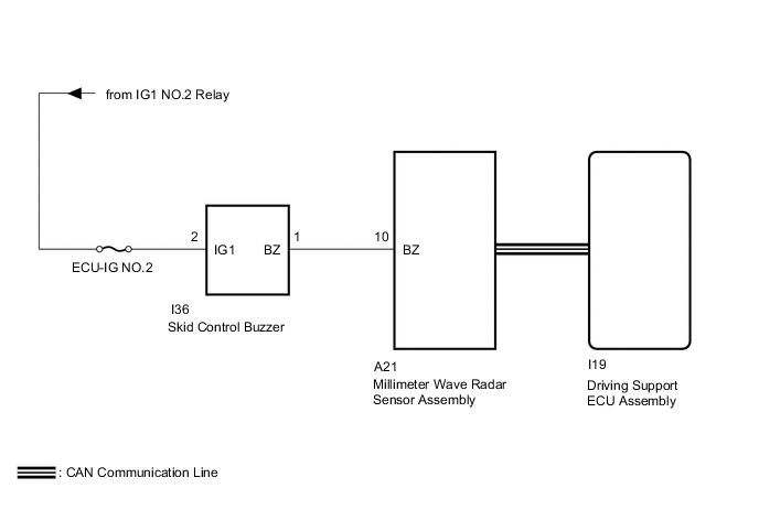
The driving support ECU assembly does this by sending a request signal to the millimeter wave radar sensor assembly to sound the skid control buzzer.
When the millimeter wave radar sensor assembly detects a malfunction in the skid control buzzer circuit, a malfunction signal is sent to the driving support ECU assembly, and this DTC is stored.
| DTC No. | Detection Item | DTC Detection Condition | Trouble Area |
|---|---|---|---|
| C1A4A | Skid Control Buzzer Circuit | While the engine switch is on (IG), a skid control buzzer circuit malfunction signal is received from the millimeter wave radar sensor assembly for 3 seconds or more. |
|
WIRING DIAGRAM
CAUTION / NOTICE / HINT
Note
-
Inspect the fuses for circuits related to this system before performing the following procedure.
-
When replacing the driving support ECU assembly, make sure to replace it with a new one. If a device which was installed to another vehicle is used, the information stored in the driving support ECU assembly will not match the information from the vehicle, and as a result, a DTC may be stored.
-
When the millimeter wave radar sensor assembly is replaced with a new one, adjustment of the radar sensor beam axis must be performed.
PROCEDURE
-
CHECK FOR DTC
-
Clear the DTCs.
Powertrain > Radar Cruise > Clear DTCs -
Make sure that the DTC detection conditions are met.
Tech Tips
If the detection conditions are not met, the system cannot detect the malfunction.
-
Check for DTCs.
Powertrain > Radar Cruise > Trouble CodesResult Result Proceed to DTC C1A4A is not output A DTC C1A4A is output B DTC C1A4A and U0235 are output C DTC C1A4A and U1104 are output D
A 
USE SIMULATION METHOD TO CHECK Click here
C
GO TO DTC U0235 Click here
D
GO TO DTC U1104 Click here
B 
-
-
PERFORM ACTIVE TEST USING GTS (RADAR CRUISE APPROACH ALARM BUZZER)
-
Connect the GTS to the DLC3.
-
Turn the engine switch on (IG).
-
Turn the GTS on.
-
Enter the following menus: Body Electrical / Pre-Crash 2 / Active Test.
-
Perform "Active Test" according to the display on GTS.
Body Electrical > Pre-Crash 2 > Active TestTester Display Measurement Item Control Range Diagnostic Note Radar Cruise Approach Alarm Buzzer Skid control buzzer ON or OFF Buzzer can be heard
Body Electrical > Pre-Crash 2 > Active TestTester Display Radar Cruise Approach Alarm Buzzer OK Skid control buzzer sounds. Result Proceed to OK NG
OK
REPLACE DRIVING SUPPORT ECU ASSEMBLY Click here
NG
-
-
INSPECT SKID CONTROL BUZZER
-
Remove the skid control buzzer.
-
Inspect the skid control buzzer.
Result Proceed to OK NG
NG
REPLACE SKID CONTROL BUZZER Click here
OK
-
-
CHECK HARNESS AND CONNECTOR (SKID CONTROL BUZZER - BATTERY)
-
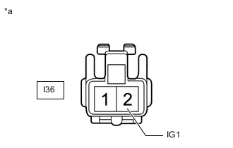
*a Front view of wire harness connector
(to Skid Control Buzzer)
Disconnect the skid control buzzer connector.
-
Measure the voltage according to the value(s) in the table below.
Standard Voltage Tester Connection Switch Condition Specified Condition I36-2 (IG1) - Body ground Engine switch on (IG) 11 to 14 V I36-2 (IG1) - Body ground Engine switch off Below 1 V Result Proceed to OK NG
NG
REPAIR OR REPLACE HARNESS OR CONNECTOR
OK
-
-
CHECK HARNESS AND CONNECTOR (SKID CONTROL BUZZER - MILLIMETER WAVE RADAR SENSOR ASSEMBLY)
-
Disconnect the I36 skid control buzzer connector.
-
Disconnect the A21 millimeter wave radar sensor assembly connector.
-
Measure the resistance according to the value(s) in the table below.
Standard Resistance Tester Connection Condition Specified Condition I36-1 (BZ) - A21-10 (BZ) Always Below 1 Ω I36-1 (BZ) or A21-10 (BZ) - Body ground Always 10 kΩ or higher Result Proceed to OK NG
NG
REPAIR OR REPLACE HARNESS OR CONNECTOR
OK
-
-
REPLACE MILLIMETER WAVE RADAR SENSOR ASSEMBLY
-
Replace the millimeter wave radar sensor assembly with a new one.
-
Perform millimeter wave radar sensor assembly adjustment.
Result Proceed to NEXT
NEXT
-
-
CHECK FOR DTC
-
Clear the DTCs.
Powertrain > Radar Cruise > Clear DTCs -
Make sure that the DTC detection conditions are met.
Tech Tips
If the detection conditions are not met, the system cannot detect the malfunction.
-
Check for DTCs.
Powertrain > Radar Cruise > Trouble CodesResult Result Proceed to DTC C1A4A is not output A DTC C1A4A is output B
A
END (MILLIMETER WAVE RADAR SENSOR ASSEMBLY WAS DEFECTIVE)
B
REPLACE DRIVING SUPPORT ECU ASSEMBLY Click here
-