DYNAMIC RADAR CRUISE CONTROL SYSTEM, Diagnostic DTC:C1A4B
| DTC Code | DTC Name |
|---|---|
| C1A4B | Stop Light Relay Circuit |
DESCRIPTION
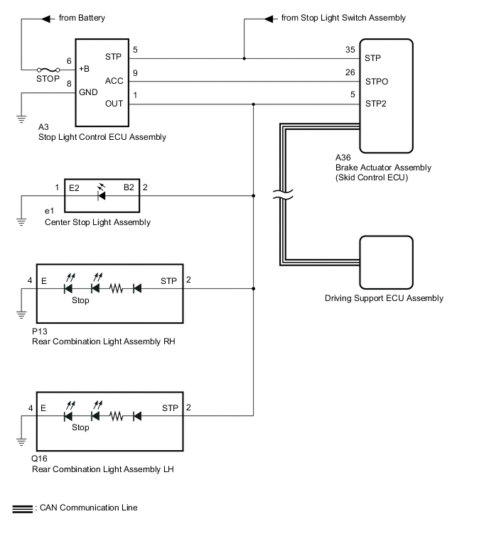
The brake actuator assembly (skid control ECU) sends a stop light operation signal to the stop light control ECU assembly. When the brake actuator assembly (skid control ECU) detects a malfunction in the stop light circuit, the driving support ECU assembly stores DTC C1A4B.
| Vehicle Condition | |||
|---|---|---|---|
| Pattern 1 | Pattern 2 | ||
| Diagnosis Condition | +BS terminal voltage is 11 to 14 V | ○ | ○ |
| When the vehicle speed is approximately 50 km/h (30 mph) or more, the cruise control switch (ON/OFF) is on | ○ | ○ | |
| Stop Light illumination output (STPO) ON | ○ | - | |
| Stop Light illumination output (STPO) OFF | - | ○ | |
| Malfunction Status | No signal input to STP2 terminal | ○ | - |
| Signals input to STP and STP2 terminals do not match | - | ○ | |
| Malfunction Time | 0.3 seconds or more | 0.3 seconds or more | |
| Number of Trips | - | - | |
| DTC No. | Detection Item | DTC Detection Condition | Trouble Area |
|---|---|---|---|
| C1A4B | Stop Light Relay Circuit | Either of the following conditions is met:
|
|
WIRING DIAGRAM
CAUTION / NOTICE / HINT
Note
-
First perform the communication function inspections in How to Proceed with Troubleshootingto confirm that there are no CAN communication malfunctions before troubleshooting.Inspect the fuses for circuits related to this system before performing the following procedure.
-
Inspect the fuses for circuits related to this system before performing the following procedure.
-
When replacing the brake actuator assembly (skid control ECU), perform zero point calibration.
PROCEDURE
-
CHECK TERMINAL VOLTAGE (STP, STPO AND STP2 TERMINAL)
-
Turn the engine switch off.
-
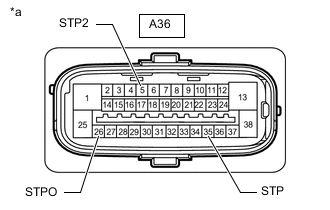
*a Front view of wire harness connector
(to Brake Actuator Assembly [Skid Control ECU])
Disconnect the brake actuator assembly (skid control ECU) connector.
-
Measure the voltage according to the value(s) in the table below.
Standard Voltage Tester Connection Condition Specified Condition A36-5 (STP2) - Body ground Brake pedal depressed 11 to 14 V Brake pedal released Below 1.5 V A36-26 (STPO) - Body ground Always 11 to 14 V A36-35 (STP) - Body ground Brake pedal depressed 11 to 14 V Brake pedal released Below 1.5 V Result Result Proceed to All terminal voltage is normal A Only STP terminal voltage abnormal B Only STPO terminal voltage abnormal C Only STP2 terminal voltage abnormal D STPO terminal and STP2 terminal voltage abnormal E
B 
REPAIR OR REPLACE HARNESS OR CONNECTOR
C 
CHECK HARNESS AND CONNECTOR (BRAKE ACTUATOR ASSEMBLY [SKID CONTROL ECU] - STOP LIGHT CONTROL ECU ASSEMBLY) Click here
D
CHECK TERMINAL VOLTAGE (STP2 TERMINAL) Click here
E
CHECK STOP LIGHT CONTROL ECU ASSEMBLY POWER SOURCE CIRCUIT Click here
A 
-
-
PERFORM ACTIVE TEST USING GTS (STOP LIGHT RELAY)
-
Enter the following menus: Chassis / ABS/VSC/TRC / Active Test.
-
Perform "Active Test" according to the display on the GTS.
Chassis > ABS/VSC/TRC > Active TestTester Display Measurement Item Control Range Diagnostic Note Stop Light Relay Stop light control ECU assembly ON or OFF Stop lights come on
Chassis > ABS/VSC/TRC > Active TestTester Display Stop Light Relay OK Stop light turns ON/OFF in response to the GTS operation Result Proceed to OK NG
NG
INSPECT BRAKE ACTUATOR ASSEMBLY (SKID CONTROL ECU) Click here
OK
-
-
CHECK FOR DTC
-
Clear the DTCs.
Powertrain > Radar Cruise > Clear DTCs -
Enter the following menus: Chassis / ABS/VSC/TRC / Active Test.
-
Perform "Active Test" according to the display on the GTS.
Chassis > ABS/VSC/TRC > Active TestTester Display Measurement Item Control Range Diagnostic Note Stop Light Relay Stop light control ECU assembly ON or OFF Stop lights come on
Chassis > ABS/VSC/TRC > Active TestTester Display Stop Light Relay -
Check for DTCs.
Powertrain > Radar Cruise > Trouble CodesResult Result Proceed to DTC C1A4B is output A DTC C1A4B is not output B
A
REPLACE BRAKE ACTUATOR ASSEMBLY (SKID CONTROL ECU) Click here
B
USE SIMULATION METHOD TO CHECK Click here
-
-
INSPECT BRAKE ACTUATOR ASSEMBLY (SKID CONTROL ECU)
-
Enter the following menus: Chassis / ABS/VSC/TRC / Active Test.
-
Perform "Active Test" according to the display on the GTS.
Chassis > ABS/VSC/TRC > Active TestTester Display Measurement Item Control Range Diagnostic Note Stop Light Relay Stop light control ECU assembly ON or OFF Stop lights come on
Chassis > ABS/VSC/TRC > Active TestTester Display Stop Light Relay -
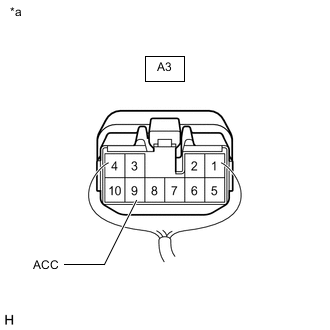
*a Component with harness connected
(Stop Light Control ECU Assembly)
Measure the voltage according to the value(s) in the table below.
Standard Voltage Tester Connection Condition Specified Condition A3-9 (ACC) - Body ground Active test is ON Below 1.5 V Result Proceed to OK NG
OK
REPLACE STOP LIGHT CONTROL ECU ASSEMBLY for LHD: Click here
REPLACE STOP LIGHT CONTROL ECU ASSEMBLY for RHD: Click hereNG
REPLACE BRAKE ACTUATOR ASSEMBLY (SKID CONTROL ECU) Click here
-
-
CHECK HARNESS AND CONNECTOR (BRAKE ACTUATOR ASSEMBLY [SKID CONTROL ECU] - STOP LIGHT CONTROL ECU ASSEMBLY)
-
Turn the engine switch off.
-
Disconnect the A36 brake actuator assembly (skid control ECU) connector.
-
Disconnect the A3 stop light control ECU assembly connector.
-
Measure the resistance according to the value(s) in the table below.
Standard Resistance Tester Connection Condition Specified Condition A36-26 (STPO) - A3-9 (ACC) Always Below 1 Ω Result Proceed to OK NG
OK
REPLACE STOP LIGHT CONTROL ECU ASSEMBLY for LHD: Click here
REPLACE STOP LIGHT CONTROL ECU ASSEMBLY for RHD: Click hereNG
REPAIR OR REPLACE HARNESS OR CONNECTOR
-
-
CHECK TERMINAL VOLTAGE (STP2 TERMINAL)
-
Turn the engine switch off.
-
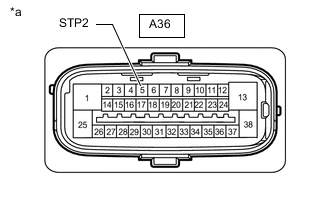
*a Front view of wire harness connector
(to Brake Actuator Assembly [Skid Control ECU])
Disconnect the brake actuator assembly (skid control ECU) connector.
-
Measure the voltage according to the value(s) in the table below.
Standard Voltage Tester Connection Condition Specified Condition A36-5 (STP2) - Body ground Brake pedal released Below 1.5 V Result Proceed to OK NG
NG
CHECK HARNESS AND CONNECTOR (BRAKE ACTUATOR ASSEMBLY [SKID CONTROL ECU] - STOP LIGHT CONTROL ECU ASSEMBLY) Click here
OK
-
-
CHECK HARNESS AND CONNECTOR (BRAKE ACTUATOR ASSEMBLY [SKID CONTROL ECU] - REAR COMBINATION LIGHT ASSEMBLY LH)
-
Turn the engine switch off.
-
Disconnect the A36 brake actuator assembly (skid control ECU) connector.
-
Disconnect the Q16 rear combination light assembly LH connector.
-
Measure the voltage according to the value(s) in the table below.
Standard Voltage Tester Connection Condition Specified Condition A36-5 (STP2) - Body ground Brake pedal depressed 11 to 14 V Result Proceed to OK NG
OK
REPLACE REAR COMBINATION LIGHT ASSEMBLY LH Click here
NG
-
-
CHECK HARNESS AND CONNECTOR (BRAKE ACTUATOR ASSEMBLY [SKID CONTROL ECU] - REAR COMBINATION LIGHT ASSEMBLY RH)
-
Turn the engine switch off.
-
Disconnect the A36 brake actuator assembly (skid control ECU) connector.
-
Disconnect the Q16 rear combination light assembly LH connector.
-
Disconnect the P13 rear combination light assembly RH connector.
-
Measure the voltage according to the value(s) in the table below.
Standard Voltage Tester Connection Condition Specified Condition A36-5 (STP2) - Body ground Brake pedal depressed 11 to 14 V Result Proceed to OK NG
OK
REPLACE REAR COMBINATION LIGHT ASSEMBLY RH Click here
NG
-
-
CHECK HARNESS AND CONNECTOR (BRAKE ACTUATOR ASSEMBLY [SKID CONTROL ECU] - CENTER STOP LIGHT ASSEMBLY)
-
Turn the engine switch off.
-
Disconnect the A36 brake actuator assembly (skid control ECU) connector.
-
Disconnect the Q16 rear combination light assembly LH connector.
-
Disconnect the P13 rear combination light assembly RH connector.
-
Disconnect the e1 center stop light assembly connector.
-
Measure the voltage according to the value(s) in the table below.
Standard Voltage Tester Connection Condition Specified Condition A36-5 (STP2) - Body ground Brake pedal depressed 11 to 14 V Result Proceed to OK NG
OK
REPLACE CENTER STOP LIGHT ASSEMBLY Click here
NG
CHECK HARNESS AND CONNECTOR (BRAKE ACTUATOR ASSEMBLY [SKID CONTROL ECU] - STOP LIGHT CONTROL ECU ASSEMBLY) Click here
-
-
CHECK HARNESS AND CONNECTOR (BRAKE ACTUATOR ASSEMBLY [SKID CONTROL ECU] - STOP LIGHT CONTROL ECU ASSEMBLY)
-
Turn the engine switch off.
-
Disconnect the A36 brake actuator assembly (skid control ECU) connector.
-
Disconnect the A3 stop light control ECU assembly connector.
-
Measure the voltage according to the value(s) in the table below.
Standard Voltage Tester Connection Condition Specified Condition A36-5 (STP2) - Body ground Brake pedal released Below 1.5 V Result Proceed to OK NG
OK
REPLACE STOP LIGHT CONTROL ECU ASSEMBLY for LHD: Click here
REPLACE STOP LIGHT CONTROL ECU ASSEMBLY for RHD: Click hereNG
CHECK HARNESS AND CONNECTOR (BRAKE ACTUATOR ASSEMBLY [SKID CONTROL ECU] - REAR COMBINATION LIGHT ASSEMBLY LH) Click here
-
-
CHECK HARNESS AND CONNECTOR (BRAKE ACTUATOR ASSEMBLY [SKID CONTROL ECU] - STOP LIGHT CONTROL ECU ASSEMBLY)
-
Turn the engine switch off.
-
Disconnect the A36 brake actuator assembly (skid control ECU) connector.
-
Disconnect the Q16 rear combination light assembly LH connector.
-
Disconnect the P13 rear combination light assembly RH connector.
-
Disconnect the e1 center stop light assembly connector.
-
Disconnect the A3 stop light control ECU assembly connector.
-
Measure the resistance according to the value(s) in the table below.
Standard Resistance Tester Connection Condition Specified Condition A3-5 (STP) - A36-35 (STP) Always Below 1 Ω A3-1 (OUT) - A36-5 (STP2) Always Below 1 Ω A3-1 (OUT) or A36-5 (STP2) - Body ground Always 10 kΩ or higher Result Proceed to OK NG
OK
REPLACE STOP LIGHT CONTROL ECU ASSEMBLY for LHD: Click here
REPLACE STOP LIGHT CONTROL ECU ASSEMBLY for RHD: Click hereNG
REPAIR OR REPLACE HARNESS OR CONNECTOR
-
-
CHECK HARNESS AND CONNECTOR (BRAKE ACTUATOR ASSEMBLY [SKID CONTROL ECU] - REAR COMBINATION LIGHT ASSEMBLY LH)
-
Turn the engine switch off.
-
Disconnect the A36 brake actuator assembly (skid control ECU) connector.
-
Disconnect the A3 stop light control ECU assembly connector.
-
Disconnect the Q16 rear combination light assembly LH connector.
-
Measure the voltage according to the value(s) in the table below.
Standard Voltage Tester Connection Condition Specified Condition A36-5 (STP2) - Body ground Brake pedal released Below 1.5 V Result Proceed to OK NG
OK
REPLACE REAR COMBINATION LIGHT ASSEMBLY LH Click here
NG
-
-
CHECK HARNESS AND CONNECTOR (BRAKE ACTUATOR ASSEMBLY [SKID CONTROL ECU] - REAR COMBINATION LIGHT ASSEMBLY RH)
-
Turn the engine switch off.
-
Disconnect the A36 brake actuator assembly (skid control ECU) connector.
-
Disconnect the A3 stop light control ECU assembly connector.
-
Disconnect the Q16 rear combination light assembly LH connector.
-
Disconnect the P13 rear combination light assembly RH connector.
-
Measure the voltage according to the value(s) in the table below.
Standard Voltage Tester Connection Condition Specified Condition A36-5 (STP2) - Body ground Brake pedal released Below 1.5 V Result Proceed to OK NG
OK
REPLACE REAR COMBINATION LIGHT ASSEMBLY RH Click here
NG
CHECK HARNESS AND CONNECTOR (BRAKE ACTUATOR ASSEMBLY [SKID CONTROL ECU] - CENTER STOP LIGHT ASSEMBLY) Click here
-
-
CHECK STOP LIGHT CONTROL ECU ASSEMBLY POWER SOURCE CIRCUIT
-
Turn the engine switch off.
-
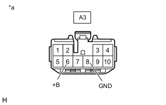
*a Front view of wire harness connector
(to Stop Light Control ECU Assembly)
Disconnect the stop light control ECU assembly connector.
-
Measure the resistance according to the value(s) in the table below.
Standard Resistance Tester Connection Condition Specified Condition A3-8 (GND) - Body ground Always Below 1 Ω -
Measure the voltage according to the value(s) in the table below.
Standard Voltage Tester Connection Condition Specified Condition A3-6 (+B) - Body ground Always 11 to 14 V Result Proceed to OK NG
NG
REPAIR OR REPLACE HARNESS OR CONNECTOR
OK
-
-
CHECK HARNESS AND CONNECTOR (BRAKE ACTUATOR ASSEMBLY [SKID CONTROL ECU] - STOP LIGHT CONTROL ECU ASSEMBLY)
-
Turn the engine switch off.
-
Disconnect the A36 brake actuator assembly (skid control ECU) connector.
-
Disconnect the A3 stop light control ECU assembly connector.
-
Measure the resistance according to the value(s) in the table below.
Standard Resistance Tester Connection Condition Specified Condition A36-26 (STPO) - A3-9 (ACC) Always Below 1 Ω Result Proceed to OK NG
OK
REPLACE STOP LIGHT CONTROL ECU ASSEMBLY for LHD: Click here
REPLACE STOP LIGHT CONTROL ECU ASSEMBLY for RHD: Click hereNG
REPAIR OR REPLACE HARNESS OR CONNECTOR
-
-
CHECK HARNESS AND CONNECTOR (BRAKE ACTUATOR ASSEMBLY [SKID CONTROL ECU] - CENTER STOP LIGHT ASSEMBLY)
-
Turn the engine switch off.
-
Disconnect the A36 brake actuator assembly (skid control ECU) connector.
-
Disconnect the A3 stop light control ECU assembly connector.
-
Disconnect the Q16 rear combination light assembly LH connector.
-
Disconnect the P13 rear combination light assembly RH connector.
-
Disconnect the e1 center stop light assembly connector.
-
Measure the voltage according to the value(s) in the table below.
Standard Voltage Tester Connection Condition Specified Condition A36-5 (STP2) - Body ground Brake pedal released Below 1.5 V Result Proceed to OK NG
OK
REPLACE CENTER STOP LIGHT ASSEMBLY Click here
NG
REPAIR OR REPLACE HARNESS OR CONNECTOR
-