CRUISE CONTROL SYSTEM(for 3ZR-FAE) TERMINALS OF ECU
-
CHECK ECM
Tech Tips
Since the ECM uses waterproof connectors, the voltage and resistance cannot be inspected directly. Standard voltage readings and resistances are indicated for reference only.
Terminal No.
(Symbol)
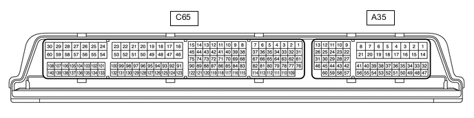
Wiring Color Terminal Description Condition Specified Condition A35-1 (BATT) - C65-59 (E1) B - BR Constant power source Always 11 to 14 V A35-10 (ST1-) - C65-59 (E1) G - BR Stop light signal Engine switch on (IG), brake pedal depressed 0 to 1.5 V Engine switch on (IG), brake pedal released 7.5 to 14 V A35-9 (STP) - C65-59 (E1) L - BR Stop light signal Brake pedal depressed 7.5 to 14 V Brake pedal released 0 to 1.5 V A35-43 (SFTD) - C65-59 (E1) GR - BR Down shift switch signal Engine switch on (IG) and shift lever M position 11 to 14 V Engine switch on (IG) and shift lever "-" position (Down shift) Below 1 V A35-42 (SFTU) - C65-59 (E1) LG - BR Up shift switch signal Engine switch on (IG) and shift lever M position 11 to 14 V Engine switch on (IG) and shift lever "+" position (Up shift) Below 1 V C65-65 (D) - C65-59 (E1) L - BR D shift position signal Engine switch on (IG) and shift lever D 11 to 14 V Engine switch on (IG) and shift lever except D Below 1 V A35-36 (CCS) - C65-59 (E1) V - BR Cruise control switch circuit Cruise control main switch off 1 MΩ or higher Cruise control main switch on Below 2.5 Ω +RES switch on 236 to 244 Ω -SET switch on 618 to 642 Ω CANCEL switch on 1510 to 1570 Ω