THERMOSTAT(for Cylinder Block) INSTALLATION
PROCEDURE
-
INSTALL THERMOSTAT (for Cylinder Block)
-
Install a new gasket to the thermostat (for Cylinder Block).
-
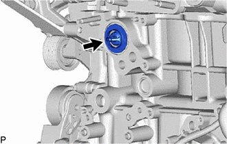
Install the thermostat (for Cylinder Block) to the cylinder block assembly in the direction shown in the illustration.
-
-
INSTALL WATER INLET HOUSING
-
Install 3 new gaskets.
-
Install the water inlet housing with the 4 bolts and nut.
- Torque:
- 21 N*m { 214 kgf*cm, 15 ft.*lbf }
-
-
INSTALL NO. 4 WATER BY-PASS PIPE
-
Temporarily install a new gasket and the No. 4 water by-pass pipe to the water inlet housing and stiffening crankcase assembly with the 2 nuts and bolt.
-
Tighten the 2 nuts and bolt.
- Torque:
- for nut
- 10 N*m { 102 kgf*cm, 7 ft.*lbf }
- for bolt
- 21 N*m { 214 kgf*cm, 15 ft.*lbf }
-
Connect the No. 4 water by-pass hose to the No. 4 water by-pass pipe, and slide the clamp to secure the hose.
-
-
INSTALL NO. 1 WATER BY-PASS PIPE
-
Temporarily install a new gasket and the No. 1 water by-pass pipe to the water inlet housing, cylinder block assembly and No. 4 water by-pass pipe with the 2 nuts and 3 bolts.
-
Tighten the 2 nuts and 3 bolts.
- Torque:
- 10 N*m { 102 kgf*cm, 7 ft.*lbf }
-
Connect the connector and install the No. 7 engine wire to the oil pressure switching valve assembly.
-
Connect the No. 5 water by-pass hose to the No. 1 water by-pass pipe, and slide the clamp to secure the hose.
-
Connect the No. 7 water by-pass hose to the No. 1 water by-pass pipe, and slide the clamp to secure the hose.
-
Connect the No. 2 water by-pass hose to the No. 1 water by-pass pipe, and slide the clamp to secure the hose.
-
Connect the water hose sub-assembly to the No. 1 water by-pass pipe, and slide the clamp to secure the hose.
-
-
INSTALL NO. 4 EXHAUST MANIFOLD HEAT INSULATOR
-
Install the No. 4 exhaust manifold heat insulator with the 2 bolts.
- Torque:
- 10 N*m { 102 kgf*cm, 7 ft.*lbf }
-
-
INSTALL NO. 3 EXHAUST MANIFOLD HEAT INSULATOR
-
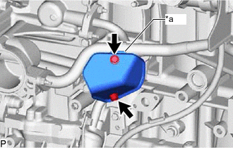
*a Protrusion Install the No. 3 exhaust manifold heat insulator with the 2 bolts.
- Torque:
- 10 N*m { 102 kgf*cm, 7 ft.*lbf }
Tech Tips
Install the part so that the protrusion faces upward.
-
-
INSTALL ENGINE OIL LEVEL DIPSTICK GUIDE
-
Install a new O-ring to the engine oil level dipstick guide.
-
Apply a light coat of engine oil to the O-ring.
-
Install the engine oil level dipstick guide with the 2 bolts.
- Torque:
- 21 N*m { 214 kgf*cm, 15 ft.*lbf }
-
Install the engine oil level dipstick.
-
-
INSTALL NO. 1 COMPRESSOR MOUNTING BRACKET
-
Install the No. 1 compressor mounting bracket with the 2 bolts and 2 nuts.
- Torque:
- 21 N*m { 214 kgf*cm, 15 ft.*lbf }
-
-
INSTALL COMPRESSOR ASSEMBLY WITH PULLEY
-
CONNECT NO. 2 RADIATOR HOSE
-
INSTALL TURBOCHARGER SUB-ASSEMBLY
-
ADD ENGINE COOLANT
-
INSPECT FOR COOLANT LEAK