WASTE GATE VALVE ACTUATOR ON-VEHICLE INSPECTION
PROCEDURE
-
INSPECT WASTE GATE VALVE ACTUATOR WITH BRACKET ASSEMBLY
-
Check the waste gate valve actuator hose for cracks and damage.
-
Check the waste gate valve actuator with bracket assembly air hole.
-
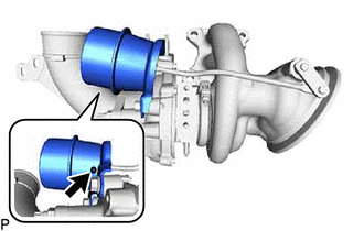
Check that the waste gate valve actuator air hole at the position shown in the illustration is open.
-
-
Check the waste gate valve actuator with bracket assembly lift amount.
-
Remove the No. 1 exhaust heat insulator.
-
Disconnect the waste gate valve actuator hose.
-
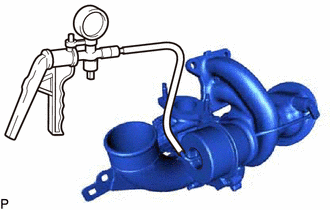
Using a vacuum pump, apply a vacuum of 35 +/- 4.0 kPa (263 +/- 35 mmHg, 10 +/- 1.2 in.Hg) to the diaphragm chamber to operate the waste gate valve actuator.
Note
Do not apply a vacuum of 65 kPa (488 mmHg, 19.2 in.Hg) or more to the waste gate valve actuator as doing so may damage the diaphragm.
Tech Tips
If the waste gate valve actuator does not operate, check whether the waste gate valve link and waste gate valve actuator are stuck.
-
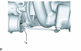
*a Paint Mark Place a paint mark on the waste gate valve actuator rod from the waste gate valve actuator bracket as shown in the illustration.
-
Using a vernier caliper, measure the length from the waste gate valve actuator bracket to the paint mark at a vacuum of 0 kPa (0 mmHg, 0 in.Hg).
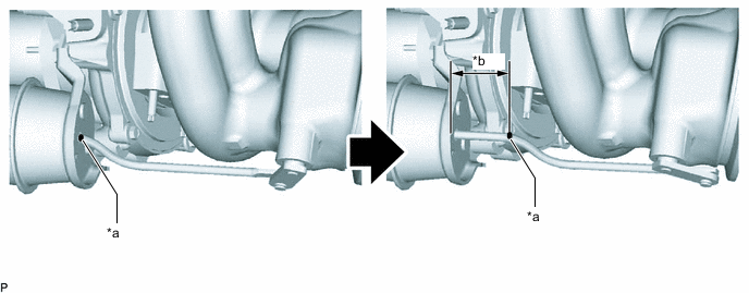
*a Paint Mark *b Waste Gate Valve Actuator Operated 
Vacuum at 0 kPa (0 mmHg, 0 in.Hg) - - Standard 21.9 to 24.7 mm (0.862 to 0.972 in.) Note
If the result is not as specified when replacing the waste gate valve actuator with bracket assembly and turbine with valve housing sub-assembly, check the lift amount of the waste gate valve actuator again.
Tech Tips
-
If the length is 21.9 mm (0.862 in.) or less, replace the waste gate valve actuator with bracket assembly.
-
If the length is 27.7 mm (0.972 in.) or more, check the waste gate valve actuator pin for wear.
If the pin wear amount is 0.5 mm (0.020 in.) or more, replace the waste gate valve actuator with bracket assembly.
If the pin wear amount is 0.5 mm (0.020 in.) or less, replace the turbine with valve housing sub-assembly.
-
-
Disconnect the vacuum pump to the waste gate valve actuator.
-
Connect the waste gate valve actuator hose.
-
Install the No. 1 exhaust heat insulator.
-
-
Check if the waste gate valve link and waste gate valve actuator is stuck.
-
Remove the waste gate valve actuator with bracket assembly.
-
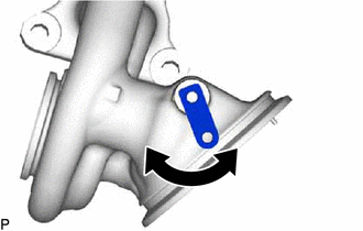
Operate the waste gate valve link by hand and check that the link moves smoothly.
If the waste gate valve link is stuck, replace the turbine with valve housing sub-assembly.
-
Operate the waste gate actuator rod by hand and check that the rod moves smoothly.
If the waste gate waste gate valve actuator rod is stuck, replace the waste gate valve actuator with bracket assembly.
-
Using a vacuum pump, apply a vacuum of 35 +/- 4.0 kPa (263 +/- 35 mmHg, 10 +/- 1.2 in.Hg) to the diaphragm chamber to operate the waste gate valve actuator.
Note
Do not apply a vacuum of 65 kPa (488 mmHg, 19.2 in.Hg) or more to the waste gate valve actuator as doing so may damage the diaphragm.
If the waste gate valve actuator does not operate with a vacuum applied, replace the waste gate valve actuator with bracket assembly.
-
Install the waste gate valve actuator with bracket assembly.
-
-
-
ADJUST WASTE GATE VALVE ACTUATOR WITH BRACKET ASSEMBLY
-
Remove the waste gate valve actuator with bracket assembly.
-
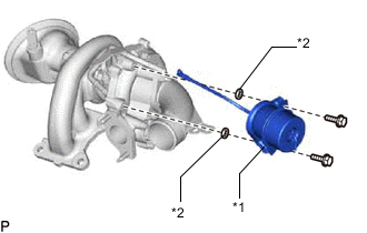
*1 Waste Gate Valve Actuator with Bracket Assembly *2 Plate Washer Install the plate washers between the waste gate valve actuator with bracket assembly and compressor sub-assembly at the positions shown in the illustration to adjust the waste gate valve actuator lift amount.
Tech Tips
Refer to the table below when selecting the appropriate combination plate washers.
Waste Gate Valve Actuator Lift Amount (mm (in.)) Required Plate Washer Thickness (mm (in.)) 21.9 to 24.7 mm (0.862 to 0.972 in.) - 24.7 to 26.2 mm (0.972 to 1.031 in.) 1.6 mm (0.063 in.) 26.2 to 27.7 mm (1.031 to 1.090 in.) 1.6 mm (0.063 in.) 2 Plate Washers -
Install the waste gate valve actuator with bracket assembly.
-
Inspect the waste gate valve actuator lift amount.
-