TURBOCHARGER INSTALLATION
PROCEDURE
-
INSTALL TURBO OIL INLET PIPE SUB-ASSEMBLY
-
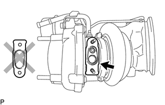
Install a new gasket as shown in the illustration.
Note
Do not install the gasket upside down.
-
Install the turbo oil inlet pipe sub-assembly with the 2 nuts.
- Torque:
- 12 N*m { 122 kgf*cm, 9 ft.*lbf }
-
-
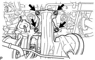
INSTALL NO. 1 TURBO WATER PIPE SUB-ASSEMBLY
-
Install a new gasket.
-
Temporarily install the No. 1 turbo water pipe sub-assembly with the bolt and 2 nuts.
-
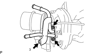
Tighten the bolt and nuts in the order shown in the illustration.
- Torque:
- for bolt
- 10 N*m { 102 kgf*cm, 7 ft.*lbf }
- for nut
- 12 N*m { 122 kgf*cm, 9 ft.*lbf }
-
-
INSTALL COMPRESSOR INLET ELBOW
-
Install a new gasket.
-
Install the compressor inlet elbow with the 2 nuts.
- Torque:
- 24 N*m { 245 kgf*cm, 18 ft.*lbf }
-
-
INSTALL TURBOCHARGER SUB-ASSEMBLY
-
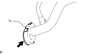
*a Claw Install a new gasket as shown in the illustration.
Note
The claws of the gasket must face the turbo oil inlet pipe sub-assembly.
-
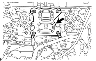
*a Protrusion Install a new gasket.
Note
The protrusion of the gasket must face the cylinder head sub-assembly.
-
Temporarily install the turbocharger sub-assembly with 4 new nuts.
-
Tighten the 4 nuts in the order shown in the illustration.
- Torque:
- 43 N*m { 438 kgf*cm, 32 ft.*lbf }
-
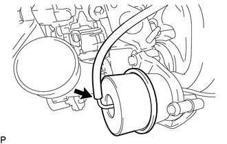
Connect the vacuum transmitting hose assembly to the waste gate valve actuator with bracket assembly.
Note
Connect the vacuum transmitting hose assembly until the bent portion of the pipe of the waste gate valve actuator with bracket assembly.
-
Connect the air by-pass valve assembly connector and wire harness clamp to the turbocharger sub-assembly.
-
-
CONNECT TURBO OIL INLET PIPE SUB-ASSEMBLY
-
Install a new gasket on the union bolt side.
-
Connect the turbo oil inlet pipe sub-assembly with the 2 bolts and union bolt.
-
Tighten the 2 bolts and union bolt.
- Torque:
- for bolt
- 10 N*m { 102 kgf*cm, 7 ft.*lbf }
- for union bolt
- 35 N*m { 357 kgf*cm, 26 ft.*lbf }
Note
If the connecting part of the union bolt gasket is cracked, remove the connecting part.
-
-
CONNECT NO. 1 TURBO WATER PIPE SUB-ASSEMBLY
-
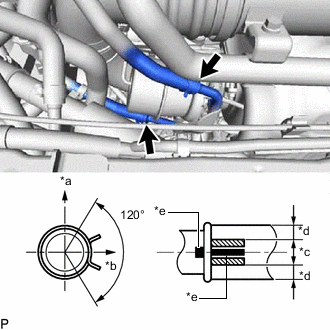
*a Upper Side *b Front of Vehicle *c OK *d NG *e Paint Mark Connect the No. 1 turbo water hose and No. 2 turbo water hose to the No. 1 turbo water pipe sub-assembly and slide the 2 clips to secure the hoses.
Note
The turbocharger sub-assembly may be damaged if the No. 1 turbo water hose and No. 2 turbo water hose are connected to the wrong locations.
Tech Tips
-
Make sure that the clips of the No. 1 turbo water hose and No. 2 turbo water hose are positioned as shown in the illustration.
-
Make sure that the paint mark of the No. 1 turbo water hose is positioned as shown in the illustration.
-
Make sure that the paint mark of the No. 2 turbo water hose is positioned the front of the vehicle.
-
-
-
INSPECT WASTE GATE VALVE ACTUATOR WITH BRACKET ASSEMBLY
-
INSTALL EXHAUST MANIFOLD CONVERTER SUB-ASSEMBLY
-
ADD ENGINE OIL
-
ADD COOLANT (for Intercooler)
-
INSPECT ENGINE OIL LEVEL
-
INSPECT FOR COOLANT LEAK (for Intercooler)
-
INSPECT FOR OIL LEAK
-
EXHAUST GAS LEAK