INTAKE MANIFOLD INSTALLATION
PROCEDURE
-
INSTALL VACUUM SURGE TANK
-
Install the vacuum surge tank with the 3 bolts.
- Torque:
- 10 N*m { 102 kgf*cm, 7 ft.*lbf }
-
-
INSTALL NO. 4 VACUUM TRANSMITTING HOSE ASSEMBLY
-
Install the No. 4 vacuum transmitting hose assembly to the vacuum surge tank and attach the 2 clamps.
-
-
INSTALL VACUUM REGULATING VALVE ASSEMBLY
-
INSTALL NO. 1 TURBO PRESSURE SENSOR
-
Install the No. 1 turbo pressure sensor with the bolt.
- Torque:
- 9.0 N*m { 92 kgf*cm, 80 in.*lbf }
-
-
INSTALL NO. 3 VACUUM TRANSMITTING HOSE ASSEMBLY
-
Install the No. 3 vacuum transmitting hose assembly to the vacuum surge tank and attach the 2 clamps.
-
-
INSTALL BRACKET
-
Install the bracket to the intake manifold with the bolt.
- Torque:
- 10 N*m { 102 kgf*cm, 7 ft.*lbf }
-
-
INSTALL NO. 2 FUEL VAPOR FEED HOSE
-
Install the No. 2 fuel vapor feed hose to the intake manifold and slide the clamp to secure the hose.
-
-
INSTALL INTAKE MANIFOLD
-
When replacing a new intercooler support bracket sub-assembly:
Temporarily install the intake manifold.
Note
If temporary installation is not performed, parts may not be correctly positioned. As a result, connecting parts may not be airtight.
-
Temporarily install a new intercooler support bracket sub-assembly to the intake manifold with the 2 bolts.
- Torque:
- 10 N*m { 102 kgf*cm, 7 ft.*lbf }
-
Temporarily install the throttle body with motor assembly.
-
Tighten the 2 bolts of the intercooler support bracket sub-assembly.
-
Remove the throttle body with motor assembly.
-
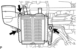
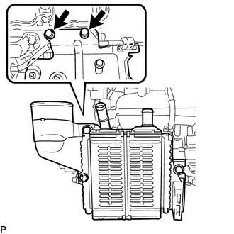
Remove the 3 bolts and intercooler assembly from the intercooler support bracket sub-assembly.
-
Install the wire harness clamp bracket with the bolt.
- Torque:
- 8.0 N*m { 82 kgf*cm, 71 in.*lbf }
-
-
When reusing intercooler support bracket sub-assembly:
Install the intercooler support bracket sub-assembly with the 2 bolts.
- Torque:
- 10 N*m { 102 kgf*cm, 7 ft.*lbf }
Note
Align the intercooler support bracket sub-assembly with its marked original position and install it.
-
Install the wire harness clamp bracket with the bolt.
- Torque:
- 8.0 N*m { 82 kgf*cm, 71 in.*lbf }
-
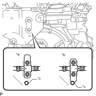
*a OK *b NG *c Stopper Install the No. 1 water by-pass hose and No. 2 water by-pass hose to the intercooler support bracket sub-assembly with the 2 nuts.
- Torque:
- 10 N*m { 102 kgf*cm, 7 ft.*lbf }
Note
Make sure that the stopper is not contacted as shown in the illustration.
-
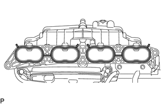
Install 2 new intake manifold gaskets to the intake manifold.
-
Temporarily install the intake manifold with the 3 bolts and 2 nuts.
-
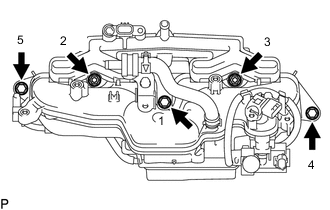
Tighten the 3 bolts and 2 nuts in the order shown in the illustration.
- Torque:
- 21 N*m { 214 kgf*cm, 15 ft.*lbf }
-
Install the bolt.
- Torque:
- 21 N*m { 214 kgf*cm, 15 ft.*lbf }
-
-
CONNECT THROTTLE BODY WATER BY-PASS HOSE
-
Connect the No. 2 water by-pass hose to the No. 1 water by-pass pipe and slide the clamp to secure the hose.
-
Connect the No. 1 water by-pass hose to the cylinder head sub-assembly and slide the clamp to secure the hose.
-
-
INSTALL NO. 2 PCV HOSE
-
Install the No. 2 PCV hose to the intake manifold and cylinder head sub-assembly and slide the 2 clamps to secure the hose.
-
-
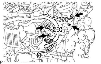
CONNECT VACUUM TRANSMITTING HOSE ASSEMBLY
-
Attach the 5 clamps and connect the vacuum transmitting hose assembly to the cylinder head cover sub-assembly.
-
Connect the vacuum transmitting hose assembly to the waste gate valve actuator.
Note
Connect the vacuum transmitting hose assembly until the bent portion of the pipe of the waste gate valve actuator.
-
-
INSTALL NO. 1 VACUUM TRANSMITTING HOSE
-
Attach the clamp and install the No. 1 vacuum transmitting hose to the intake manifold.
-
-
INSTALL NO. 2 TURBO PRESSURE SENSOR
-
CONNECT NO. 2 VACUUM TRANSMITTING HOSE ASSEMBLY
-
Install the No. 2 vacuum transmitting hose assembly to the vacuum pump assembly and cylinder head cover sub-assembly with the clamp.
-
-
INSTALL NO. 2 WATER BY-PASS PIPE
-
Install the No. 2 water by-pass pipe to the cylinder head cover sub-assembly and No. 2 vacuum switching valve bracket with the 3 bolts.
- Torque:
- 10 N*m { 102 kgf*cm, 7 ft.*lbf }
-
-
CONNECT ENGINE WIRE
-
Attach the 2 clamps and connect the 3 connectors to connect the engine wire.
-
Install the ground bolt.
- Torque:
- 8.4 N*m { 86 kgf*cm, 74 in.*lbf }
-
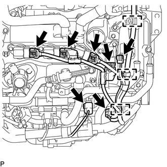
Connect the 7 connectors and attach the 3 clamps.
-
Connect the wire harness clamp and install the wire harness with the bolt.
- Torque:
- 8.0 N*m { 82 kgf*cm, 71 in.*lbf }
-
Install the bolt and nut to the wire harness bracket.
- Torque:
- 8.0 N*m { 82 kgf*cm, 71 in.*lbf }
-
Connect the 3 connectors and attach the clamp.
-
-
CONNECT WATER BY-PASS HOSE
-
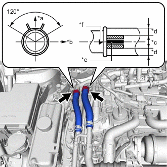
*a Upper Side *b Left Side *c OK *d NG *e Paint Mark *f Water By-pass Pipe Matchmark Connect the No. 5 sub-radiator hose and No. 6 sub-radiator hose to the No. 2 water by-pass pipe with the 2 clips to secure the hoses.
Tech Tips
-
Install the sub-radiator hoses and clips as shown in the illustration.
-
Position the paint mark as illustrated.
-
-
-
INSTALL PURGE VSV
-
INSTALL OUTER COWL TOP PANEL (for LHD)
-
Install the outer cowl top panel with the 13 bolts.
- Torque:
- 5.5 N*m { 56 kgf*cm, 49 in.*lbf }
-
Attach the 4 clamps and connect the wire harness.
-
Connect the connector.
-
-
INSTALL OUTER COWL TOP PANEL (for RHD)
-
Install the outer cowl top panel with the 13 bolts.
- Torque:
- 5.5 N*m { 56 kgf*cm, 49 in.*lbf }
-
Attach the 4 clamps and connect the wire harness.
-
Connect the connector.
-
-
INSTALL SUSPENSION TOWER DAMPER (w/ Performance Damper)
-
Install the suspension tower damper with the 2 nuts.
- Torque:
- 20 N*m { 204 kgf*cm, 15 ft.*lbf }
-
-
INSTALL SUSPENSION TOWER DAMPER (w/o Performance Damper)
-
INSTALL WINDSHIELD WIPER MOTOR ASSEMBLY
-
INSTALL GENERATOR ASSEMBLY
-
INSTALL INTERCOOLER ASSEMBLY
-
INSPECT FOR COOLANT LEAK
-
INSPECT FOR COOLANT LEAK (for Intercooler)