INTAKE MANIFOLD REMOVAL
PROCEDURE
-
REMOVE INTERCOOLER ASSEMBLY
-
REMOVE GENERATOR ASSEMBLY
-
REMOVE WINDSHIELD WIPER MOTOR ASSEMBLY
-
REMOVE SUSPENSION TOWER DAMPER (w/ Performance Damper)
-
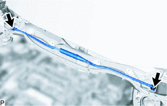
Remove the 2 nuts and suspension tower damper.
-
-
REMOVE SUSPENSION TOWER DAMPER (w/o Performance Damper)
-
REMOVE OUTER COWL TOP PANEL (for LHD)
-
Disconnect the connector.
-
Detach the 4 clamps and disconnect the wire harness.
-
Remove the 13 bolts and outer cowl top panel.
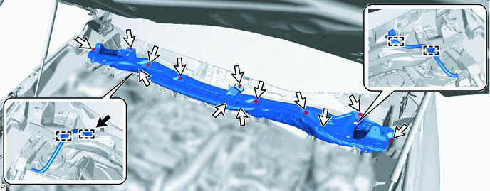

Connector 
Bolt
-
-
REMOVE OUTER COWL TOP PANEL (for RHD)
-
Disconnect the connector.
-
Detach the 4 clamps and disconnect the wire harness.
-
Remove the 13 bolts and outer cowl top panel.
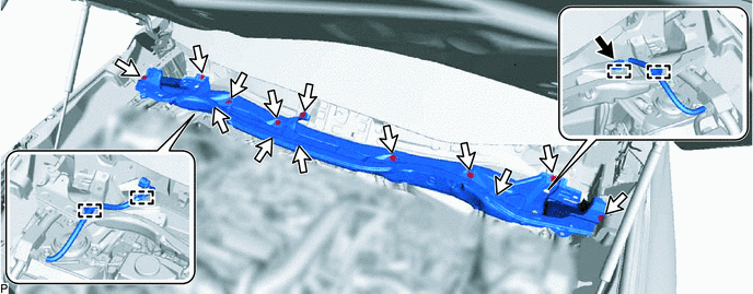
Connector Bolt
-
-
REMOVE PURGE VSV
-
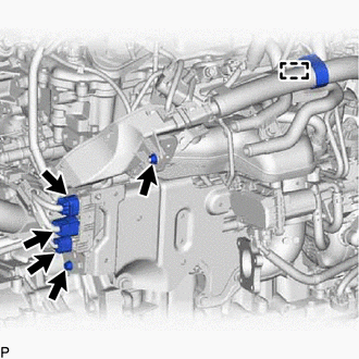
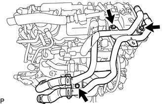
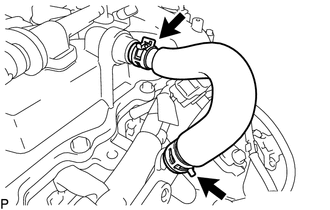
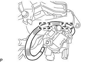
DISCONNECT WATER BY-PASS HOSE
-
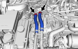
Slide the 2 clips and disconnect the No. 5 sub-radiator hose and No. 6 sub-radiator hose from the No. 2 water by-pass pipe.
-
-
DISCONNECT ENGINE WIRE
-
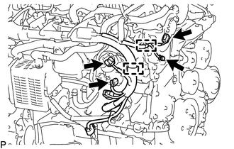
Disconnect the 3 connectors and detach the wire harness clamp.
-
Remove the bolt and nut from the wire harness bracket.
-
Remove the bolt, detach the wire harness clamp and disconnect the wire harness.
-
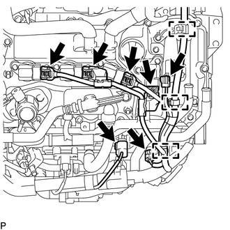
Disconnect the 7 connectors and detach the 3 clamps.
-
Disconnect the 3 connectors, detach the 2 clamps and disconnect the engine wire.
-
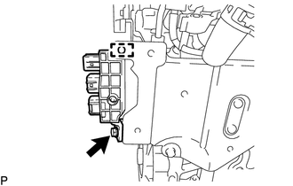
Remove the ground bolt.
-
-
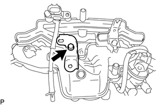
REMOVE NO. 2 WATER BY-PASS PIPE
-
Remove the 3 bolts and No. 2 water by-pass pipe from the cylinder head cover sub-assembly and No. 2 vacuum switching valve bracket.
-
-
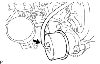
DISCONNECT NO. 2 VACUUM TRANSMITTING HOSE ASSEMBLY
-
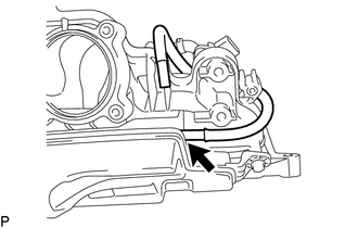
Detach the clamp and disconnect the No. 2 vacuum transmitting hose assembly from the vacuum pump assembly and cylinder head cover sub-assembly.
-
-
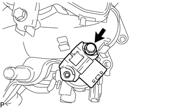
REMOVE NO. 2 TURBO PRESSURE SENSOR
-
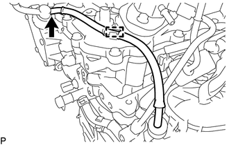
REMOVE NO. 1 VACUUM TRANSMITTING HOSE
-
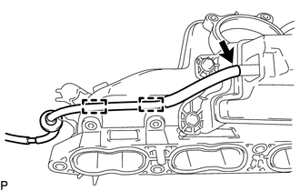
Detach the clamp and disconnect the No. 1 vacuum transmitting hose from the intake manifold.
-
-
DISCONNECT VACUUM TRANSMITTING HOSE ASSEMBLY
-
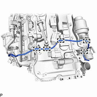
Detach the 5 clamps and disconnect the vacuum transmitting hose assembly from the cylinder head cover sub-assembly.
-
Disconnect the vacuum transmitting hose assembly from the waste gate valve actuator with bracket assembly.
-
-
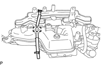
REMOVE NO. 2 PCV HOSE
-
Slide the 2 clamps and remove the No. 2 PCV hose from the intake manifold and cylinder head cover sub-assembly.
-
-
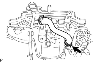
DISCONNECT THROTTLE BODY WATER BY-PASS HOSE
-
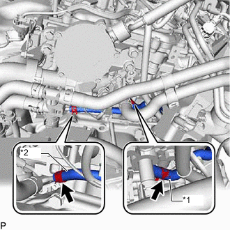
*1 No. 1 Water By-pass Hose *2 No. 2 Water By-pass Hose Slide the clamp and disconnect the No. 2 water by-pass hose from the No. 1 water by-pass pipe.
-
Slide the clamp and disconnect the No. 1 water by-pass hose from the cylinder head sub-assembly.
-
-
REMOVE INTAKE MANIFOLD
-
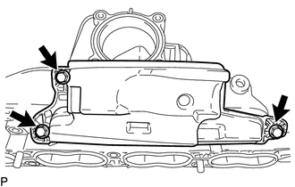
Remove the bolt.
-
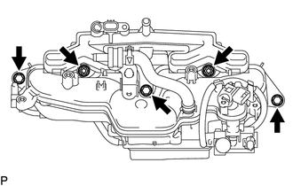
Remove the 3 bolts, 2 nuts and intake manifold.
-
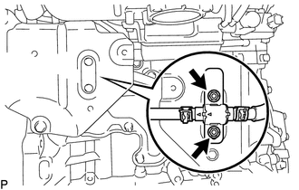
Remove the 2 nuts, No. 1 water by-pass hose and No. 2 water by-pass hose.
-
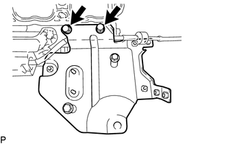
Remove the 2 bolts and intercooler support bracket sub-assembly.
Note
Align the intercooler support bracket sub-assembly with its marked original position and removal it.
-
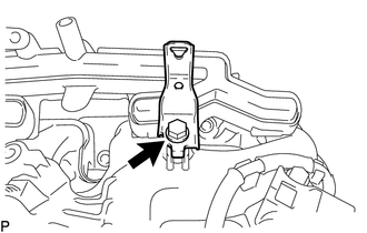
Remove the bolt and bracket wire harness clamp bracket.
-
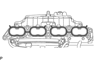
Remove the 2 intake manifold gaskets from the intake manifold.
-
-
REMOVE NO. 2 FUEL VAPOR FEED HOSE
-
Slide the clamp and remove the No. 2 fuel vapor feed hose from the intake manifold.
-
-
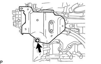
REMOVE BRACKET
-
Remove the bolt from the intake manifold.
-
-
REMOVE NO. 3 VACUUM TRANSMITTING HOSE ASSEMBLY
-
Detach the 2 clamps.
-
Remove the No. 3 vacuum transmitting hose from the vacuum surge tank.
-
-
REMOVE NO. 1 TURBO PRESSURE SENSOR
-
Remove the bolt and No. 1 turbo pressure sensor.
-
-
REMOVE VACUUM REGULATING VALVE ASSEMBLY
-
REMOVE NO. 4 VACUUM TRANSMITTING HOSE ASSEMBLY
-
Detach the 2 clamps and remove the No. 4 vacuum transmitting hose assembly from the vacuum surge tank.
-
-
REMOVE VACUUM SURGE TANK
-
Remove the 3 bolts and vacuum surge tank.
-