TURBOCHARGER REASSEMBLY
PROCEDURE
-
INSTALL PIN
Tech Tips
Replace the pin if it is deformed or damaged.
-
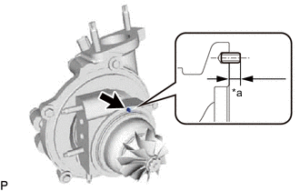
*a Standard Protrusion Amount Using a hammer, tap in the pin to the standard protrusion amount at the position shown in the illustration.
Standard protrusion amount 2.9 to 3.8 mm (0.114 to 0.150 in.)
-
-
INSTALL STUD BOLT
Tech Tips
Replace the stud bolt if it is deformed or its threads are damaged.
-
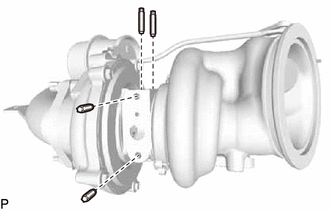
Using an E5 "TORX" socket wrench, install the 4 stud bolts at the positions shown in the illustration.
- Torque:
- 5.5 N*m { 56 kgf*cm, 49 in.*lbf }
-

Using an E8 "TORX" socket wrench, install the 4 stud bolts at the positions shown in the illustration.
- Torque:
- 10 N*m { 102 kgf*cm, 7 ft.*lbf }
-
-
INSTALL COMPRESSOR WITH BEARING HOUSING SUB-ASSEMBLY
Note
After removal and installation of the waste gate valve actuator with bracket assembly, make sure to check the waste gate valve actuator lift amount.
-
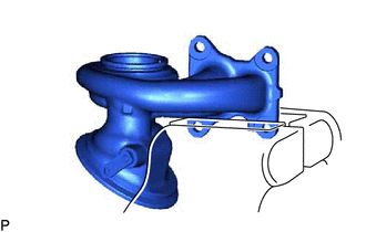
Secure the flange of the turbine with valve housing sub-assembly of the turbocharger sub-assembly in a vise between aluminum plates.
Note
Do not tighten the vise more than necessary, as doing so will damage the flange of the turbine with valve housing sub-assembly.
-
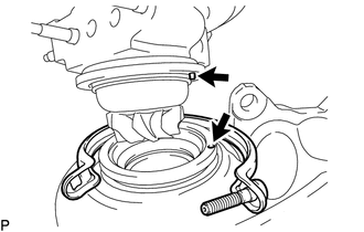
Align the position of the pin to install the compressor with bearing housing sub-assembly.
Note
When installing, do not damage the turbine with valve housing sub-assembly and turbine.
-
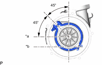
*a Turbo Water Pipe Installation Surface *b Turbo Oil Inlet Pipe Installation Surface Set a new V band so that the opening is positioned as shown in the illustration.
Note
Do not reuse the V band and nut.
-
Tighten the nut.
- Torque:
- 5.0 N*m { 51 kgf*cm, 44 in.*lbf }
-
-
INSTALL AIR BY-PASS VALVE ASSEMBLY
-
INSTALL WASTE GATE VALVE ACTUATOR WITH BRACKET ASSEMBLY
Note
After removal and installation of the waste gate valve actuator with bracket assembly, make sure to check the waste gate valve actuator lift amount.
-
Install the waste gate valve actuator with bracket assembly with the 2 bolts.
- Torque:
- 24 N*m { 245 kgf*cm, 18 ft.*lbf }
-
Install a new E-washer to the waste gate valve actuator with bracket assembly link pin.
Note
Do not reuse the E-washer.
-