PURGE VALVE INSPECTION
PROCEDURE
-
INSPECT PURGE VSV
-
Measure the resistance according to the value(s) in the table below.
Standard Resistance Tester Connection Condition Specified Condition 1 - 2 20°C (68°F) 23 to 26 Ω 1 - VSV body Always 10 MΩ or higher 2 - VSV body Always 10 MΩ or higher -
Check the operation of the purge VSV.
-
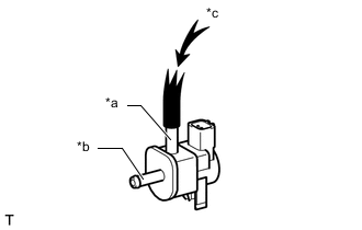
*a Port E *b Port F *c Air Check that air does not flow from port F when air is applied to port E.
-
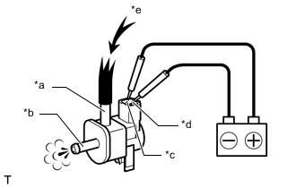
*a Port E *b Port F *c Terminal 1 *d Terminal 2 *e Air Apply battery voltage between the terminals of purge VSV, and check the purge VSV operation.
OK Measurement Condition Specified Condition Battery positive (+) → Terminal 1
Battery negative (-) → Terminal 2
Air flows from port E to port F Tech Tips
If the result is not as specified, replace the purge VSV.
-
-