MONOLITHIC CONVERTER INSTALLATION
PROCEDURE
-
INSTALL STUD BOLT
Note
If a stud bolt is deformed or its threads are damaged, replace it.
-
Using an E10 "TORX" socket wrench, install the 2 stud bolts to the exhaust manifold converter sub-assembly.
- Torque:
- 14.5 N*m { 148 kgf*cm, 11 ft.*lbf }
-
-
INSTALL EXHAUST MANIFOLD CONVERTER SUB-ASSEMBLY
-
Set a new exhaust pipe clamp to the turbocharger sub-assembly.
Note
Make sure the end of the exhaust pipe clamp does not open 140 mm or more (standard amount approximately 60 mm).
-
Temporarily install the turbocharger stay to the exhaust manifold converter sub-assembly with the nut.
Note
Tighten the nut by hand until it contacts the surface.
-
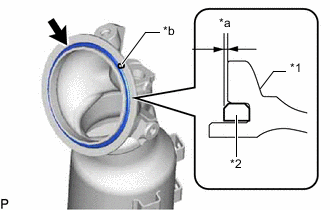
*1 Exhaust Manifold Converter Sub-assembly *2 Gasket *a 1.5 mm (0.0591 in.) or less *b Knock Pin Install a new gasket to the exhaust manifold converter sub-assembly as shown in the illustration.
Note
When reusing the exhaust manifold converter sub-assembly, thoroughly clean the gasket groove so that no old gasket remains.
Tech Tips
Fully insert the gasket into the gasket groove of the exhaust manifold converter sub-assembly.
-
Connect the turbocharger stay to the stud bolt on the cylinder head sub-assembly side and temporarily install the turbocharger stay with the nut.
Note
Tighten the nut by hand until it contacts the surface.
-
Align the exhaust manifold converter sub-assembly with the knock hole on the turbocharger sub-assembly side to connect the exhaust manifold converter sub-assembly.
-
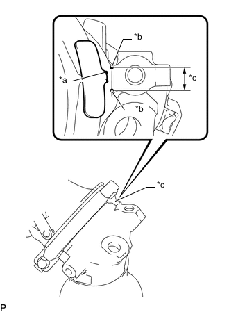
*a Alignment Protrusion on Exhaust Pipe Clamp Side *b Alignment Protrusion on Exhaust Manifold Converter Sub-assembly Side *c Position Alignment Range Align the flange surfaces of the turbocharger sub-assembly and exhaust manifold converter sub-assembly as shown in the illustration, and then temporarily install the exhaust pipe clamp.
Tech Tips
Align the position alignment protrusions on the exhaust pipe clamp side to within the range of the position alignment protrusions on the exhaust manifold converter sub-assembly side.
-
Temporarily install the manifold stay with the bolt and nut.
-
Tighten the exhaust pipe clamp.
- Torque:
- 17 N*m { 173 kgf*cm, 13 ft.*lbf }
-
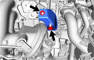
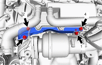
Tighten the 2 nuts in the order shown in the illustration.
- Torque:
- 43 N*m { 438 kgf*cm, 32 ft.*lbf }
-
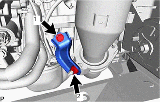
Tighten the bolt and nut in the order shown in the illustration.
- Torque:
- 43 N*m { 438 kgf*cm, 32 ft.*lbf }
-
-
INSTALL NO. 2 EXHAUST MANIFOLD HEAT INSULATOR
-
Install the No. 2 exhaust manifold heat insulator with the 4 bolts.
- Torque:
- 13.5 N*m { 138 kgf*cm, 10 ft.*lbf }
-
-
INSTALL NO. 1 EXHAUST MANIFOLD HEAT INSULATOR
-
Install the No. 1 exhaust manifold heat insulator with the 3 bolts.
- Torque:
- 15 N*m { 153 kgf*cm, 11 ft.*lbf }
-
-
INSTALL AIR FUEL RATIO SENSOR
-
INSTALL INTAKE AIR RESONATOR
-
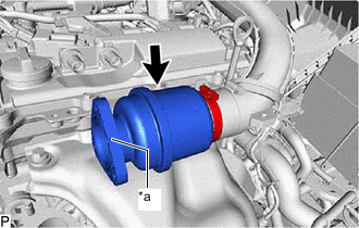
*a Gasket Groove Connect the intake air resonator to the No. 1 air hose as shown in the illustration.
Tech Tips
-
Connect the intake air resonator so that the gasket groove can be seen from the front.
-
After installing the compressor outlet elbow, tighten the hose clamp.
-
-
-
INSTALL COMPRESSOR OUTLET ELBOW
-
Install a new gasket to the intake air resonator.
-
Install a new gasket to the compressor housing sub-assembly.
-
Install the compressor outlet elbow with the 3 bolts and 2 nuts.
- Torque:
- for bolt
- 10 N*m { 102 kgf*cm, 7 ft.*lbf }
- for nut
- 24 N*m { 245 kgf*cm, 18 ft.*lbf }
-
Connect the vacuum transmitting hose assembly to the compressor outlet elbow with the 2 clamps.
-
Tighten the hose clamp of the No. 1 air hose.
- Torque:
- 6.3 N*m { 64 kgf*cm, 56 in.*lbf }
-
-
INSTALL NO. 5 EXHAUST MANIFOLD HEAT INSULATOR
-
Temporarily install the No. 5 exhaust manifold heat insulator with the 4 bolts.
Tech Tips
Temporarily install the bolts in the order shown in the illustration.
-
Tighten the 4 bolts in the order shown in the illustration.
- Torque:
- 10 N*m { 102 kgf*cm, 7 ft.*lbf }
-
-
INSTALL NO. 2 AIR CLEANER HOSE
-
Install the No. 2 air cleaner hose to the compressor inlet elbow and tighten the hose clamp.
- Torque:
- 6.3 N*m { 64 kgf*cm, 56 in.*lbf }
-
Connect the No. 4 PCV hose to the No. 2 air cleaner hose, and slide the clip to secure the hose.
-
-
INSTALL INTAKE AIR CONNECTOR
-
Install the intake air connector to the No. 2 air cleaner hose.
-
Install the 2 bolts.
- Torque:
- 21 N*m { 214 kgf*cm, 15 ft.*lbf }
-
Tighten the hose clamp.
- Torque:
- 6.3 N*m { 64 kgf*cm, 56 in.*lbf }
-
Connect the No. 1 sub-radiator hose with the 2 bolts.
- Torque:
- 10 N*m { 102 kgf*cm, 7 ft.*lbf }
-
-
INSTALL AIR CLEANER CAP WITH AIR CLEANER HOSE
-
Install the air cleaner cap with air cleaner hose to the intake air connector and tighten the hose clamp.
- Torque:
- 6.3 N*m { 64 kgf*cm, 56 in.*lbf }
-
Install the 2 hinges first, and then install the air cleaner cap sub-assembly with the 2 clamps.
-
Connect the PCV hose to the air cleaner hose, and slide the clamp to secure the hose.
-
Attach the wire harness clamp to the air cleaner cap sub-assembly.
-
Connect the mass air flow meter connector.
-
-
INSTALL FRONT EXHAUST PIPE SUB-ASSEMBLY
-
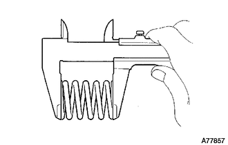
Using a vernier caliper, measure the free length of the compression spring.
Minimum length 41.5 mm (1.63 in.) If the length is less than the minimum, replace the compression spring.
-
Using a wire brush, remove any foreign matter from the gasket installation surface.
-
*1 Exhaust Manifold Converter Sub-assembly *2 Gasket *a Wooden Block Using a plastic-faced hammer and wooden block, tap in a new gasket until its surface is flush with the exhaust manifold converter sub-assembly.
Note
-
Be sure to install the gasket so that it faces the correct direction.
-
Do not reuse the gasket.
-
Do not damage the gasket.
-
When connecting the front exhaust pipe assembly, do not push in the gasket with the front exhaust pipe assembly.
-
-
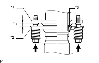
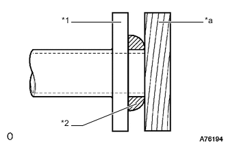
*1 Exhaust Manifold Converter Sub-assembly *2 Front Exhaust Pipe Sub-assembly *3 Gasket *a Space between flanges: 8.5 mm (0.335 in.) Install the front exhaust pipe sub-assembly to the exhaust manifold converter sub-assembly with the 2 compression springs and 2 bolts.
- Torque:
- 43 N*m { 438 kgf*cm, 32 ft.*lbf }
-
Install a new gasket to the front exhaust pipe sub-assembly.
-
Connect the front exhaust pipe sub-assembly to the front No. 2 exhaust pipe sub-assembly with the 2 new nuts and 2 bolts.
- Torque:
- 43 N*m { 438 kgf*cm, 32 ft.*lbf }
-
-
INSPECT FOR EXHAUST GAS LEAK
-
INSTALL NO. 1 ENGINE UNDER COVER ASSEMBLY
-
INSTALL NO. 1 ENGINE COVER SUB-ASSEMBLY