REAR UPPER ARM INSTALLATION
CAUTION / NOTICE / HINT
Tech Tips
-
Use the same procedure for the RH and LH sides.
-
The procedure listed below is for the LH side.
PROCEDURE
-
TEMPORARILY INSTALL REAR UPPER CONTROL ARM ASSEMBLY LH
-
Temporarily install the rear upper control arm to the rear suspension member with the bolt and nut.
-
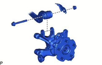
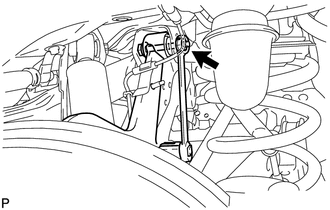
Temporarily install the rear upper control arm to the rear axle carrier with the bolt, parking brake wire bracket and nut.
Note
-
Since a stopper nut is used, tighten the bolt.
-
Do not damage the boot of the rear upper control arm assembly LH.
-
-
-
STABILIZE SUSPENSION
-
TIGHTEN REAR UPPER CONTROL ARM ASSEMBLY LH
-
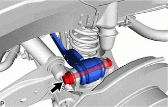
Tighten the bolt of the upper control arm.
- Torque:
- 90 N*m { 918 kgf*cm, 66 ft.*lbf }
-
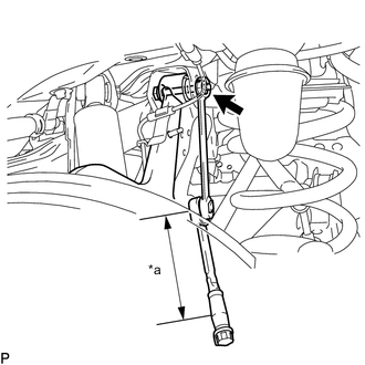
*a Torque Wrench Fulcrum Length Using a 19 mm ball joint lock nut wrench, tighten the bolt on the rear upper control arm assembly LH.
- Torque:
- Specified tightening torque
- 90 N*m { 918 kgf*cm, 66 ft.*lbf }
Tech Tips
-
Calculate the torque wrench reading when changing the fulcrum length of the torque wrench.
-
When using a ball joint lock nut wrench (fulcrum length of 150 mm (5.9055 in.)) + torque wrench (fulcrum length of 400 mm (15.7480 in.)): 65.5 N*m (668 kgf*cm, 48 ft.*lbf)
-
-
CONNECT PARKING BRAKE WIRE ASSEMBLY NO.1
-
CONNECT REAR SKID CONTROL SENSOR WIRE LH (for 2WD)
-
w/o AVS:
-
w/ AVS:
-
-
CONNECT REAR SPEED SENSOR LH (for AWD)
-
w/o AVS:
-
w/ AVS:
-
-
INSTALL REAR SUSPENSION ARM COVER LH
-
INSTALL REAR WHEEL
-
INSPECT AND ADJUST REAR WHEEL ALIGNMENT
-
PERFORM INITIALIZATION