SFI SYSTEM(w/o Canister Pump Module), Diagnostic DTC:P003373
| DTC Code | DTC Name |
|---|---|
| P003373 | Turbocharger / Supercharger Bypass Valve "A" Control Actuator Stuck Closed |
DESCRIPTION
Refer to DTC P003312.
| DTC No. | Detection Item | DTC Detection Condition | Trouble Area | MIL | Memory | Note |
|---|---|---|---|---|---|---|
| P003373 | Turbocharger / Supercharger Bypass Valve "A" Control Actuator Stuck Closed | The boost pressure does not drop despite control to open the air by-pass valve assembly (1 trip detection logic). |
|
- | DTC stored | SAE: P0039 |
MONITOR DESCRIPTION
If the throttle valve is closed while the boost pressure is applied, the air by-pass valve assembly opens and the excess pressure between the turbocharger and the throttle valve is released. If the boost pressure does not drop for a certain amount of time despite control to open the air by-pass valve assembly, the ECM determines that the air by-pass valve assembly is stuck closed and stores a DTC.
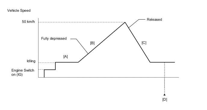
CONFIRMATION DRIVING PATTERN
-
Connect the GTS to the DLC3.
-
Turn the engine switch on (IG) and turn the GTS on.
-
Clear the DTCs (even if no DTCs are stored, perform the clear DTC procedure).
-
Turn the engine switch off and wait for at least 30 seconds.
-
Turn the engine switch on (IG) and turn the GTS on.
-
Start the engine and warm it up until the engine coolant temperature reaches 75°C (167°F) or higher [A].
-
Accelerate to 50 km/h (31 mph) or more with the accelerator pedal fully depressed [B].
CAUTION:
When performing the confirmation driving pattern, obey all speed limits and traffic laws.
-
Quickly release the accelerator pedal from the fully depressed position [C].
-
Enter the following menus: Powertrain / Engine / Trouble Codes [D].
-
Read the pending DTCs.
Tech Tips
-
If a pending DTC is output, the system is malfunctioning.
-
If a pending DTC is not output, perform the following procedure.
-
-
Enter the following menus: Powertrain / Engine / Utility / All Readiness.
-
Input the DTC: P003373.
-
Check the DTC judgment result.
GTS Display Description NORMAL
-
DTC judgment completed
-
System normal
ABNORMAL
-
DTC judgment completed
-
System abnormal
INCOMPLETE
-
DTC judgment not completed
-
Perform driving pattern after confirming DTC enabling conditions
N/A
-
Unable to perform DTC judgment
-
Number of DTCs which do not fulfill DTC preconditions has reached ECU memory limit
Tech Tips
-
If the judgment result shows NORMAL, the system is normal.
-
If the judgment result shows ABNORMAL, the system has a malfunction.
-
If the judgment result shows INCOMPLETE or N/A, perform steps [B] through [D] again.
-
WIRING DIAGRAM
Refer to DTC P003312 for air by-pass valve assembly circuit.
Refer to DTC P023511 for No. 2 turbo pressure sensor circuit.
CAUTION / NOTICE / HINT
Tech Tips
Read freeze frame data using the GTS. The ECM records vehicle and driving condition information as freeze frame data the moment a DTC is stored. When troubleshooting, freeze frame data can help determine if the vehicle was moving or stationary, if the engine was warmed up or not, if the air fuel ratio was lean or rich, and other data from the time the malfunction occurred.
PROCEDURE
-
CHECK ANY OTHER DTCS OUTPUT (IN ADDITION TO DTC P003373)
-
Connect the GTS to the DLC3.
-
Turn the engine switch on (IG).
-
Turn the GTS on.
-
Enter the following menus: Powertrain / Engine / Trouble Codes.
-
Read the DTCs.
Powertrain > Engine > Trouble CodesResult Result Proceed to DTC P003373 is output A DTC P003373 and other DTCs are output B Tech Tips
If any DTCs other than P003373 are output, troubleshoot those DTCs first.
B 
GO TO DTC CHART Click here
A 
-
-
INSPECT NO. 2 TURBO PRESSURE SENSOR
-
Inspect the No. 2 turbo pressure sensor.
Result Proceed to OK NG
NG 
CHECK TERMINAL VOLTAGE (POWER SOURCE OF NO. 2 TURBO PRESSURE SENSOR) Click here
OK
-
-
INSPECT AIR BY-PASS VALVE ASSEMBLY
-
Inspect the air by-pass valve assembly.
Result Proceed to OK NG
NG
REPLACE AIR BY-PASS VALVE ASSEMBLY Click here
OK
-
-
CHECK TERMINAL VOLTAGE (POWER SOURCE OF AIR BY-PASS VALVE ASSEMBLY)
-
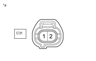
*a Front view of wire harness connector
(to Air By-pass Valve Assembly)
Disconnect the air by-pass valve assembly connector.
-
Turn the engine switch on (IG).
-
Measure the voltage according to the value(s) in the table below.
Standard Voltage Tester Connection Switch Condition Specified Condition C31-1 - Body ground Engine switch on (IG) 11 to 14 V Result Proceed to OK NG
NG
REPAIR OR REPLACE HARNESS OR CONNECTOR (AIR BY-PASS VALVE ASSEMBLY - EFI-MAIN NO. 1 RELAY)
OK
-
-
CHECK HARNESS AND CONNECTOR (AIR BY-PASS VALVE ASSEMBLY - ECM)
-
Disconnect the air by-pass valve assembly connector.
-
Disconnect the ECM connector.
-
Measure the resistance according to the value(s) in the table below.
Standard Resistance Tester Connection Condition Specified Condition C31-2 - C20-67 (ABV) Always Below 1 Ω C31-2 or C20-67 (ABV) - Body ground and other terminals Always 10 kΩ or higher Result Proceed to OK NG
NG
REPAIR OR REPLACE HARNESS OR CONNECTOR
OK
-
-
CHECK WHETHER DTC OUTPUT RECURS (P003373)
-
Connect the GTS to the DLC3.
-
Turn the engine switch on (IG).
-
Turn the GTS on.
-
Clear the DTC.
Powertrain > Engine > Clear DTCs -
Turn the engine switch off and wait for at least 30 seconds.
-
Turn the engine switch on (IG).
-
Turn the GTS on.
-
Drive the vehicle in accordance with the driving pattern described in the Confirmation Driving Pattern.
-
Enter the following menus: Powertrain / Engine / Trouble Codes.
-
Read the DTCs.
Powertrain > Engine > Trouble CodesResult Result Proceed to DTC P003373 is output A DTCs are not output B
A
REPLACE ECM Click here
B
END
-
-
CHECK TERMINAL VOLTAGE (POWER SOURCE OF NO. 2 TURBO PRESSURE SENSOR)
-
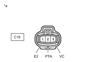
*a Front view of wire harness connector
(to No. 2 Turbo Pressure Sensor)
Disconnect the No. 2 turbo pressure sensor connector.
-
Turn the engine switch on (IG).
-
Measure the voltage according to the value(s) in the table below.
Standard Voltage Tester Connection Condition Specified Condition C15-3 (VC) - C15-1 (E2) Engine switch on (IG) 4.5 to 5.5 V C15-2 (PTA) - C15-1 (E2) Engine switch on (IG) 3.0 to 5.5 V Result Proceed to OK NG
NG
CHECK HARNESS AND CONNECTOR (NO. 2 TURBO PRESSURE SENSOR - ECM) Click here
OK
-
-
REPLACE NO. 2 TURBO PRESSURE SENSOR
-
Replace the No. 2 turbo pressure sensor.
Result Proceed to NEXT
NEXT
-
-
CHECK WHETHER DTC OUTPUT RECURS (P003373)
-
Connect the GTS to the DLC3.
-
Turn the engine switch on (IG).
-
Turn the GTS on.
-
Clear the DTC.
Powertrain > Engine > Clear DTCs -
Turn the engine switch off and wait for at least 30 seconds.
-
Turn the engine switch on (IG).
-
Turn the GTS on.
-
Drive the vehicle in accordance with the driving pattern described in the Confirmation Driving Pattern.
-
Enter the following menus: Powertrain / Engine / Trouble Codes.
-
Read the DTCs.
Powertrain > Engine > Trouble CodesResult Result Proceed to DTC P003373 is output A DTCs are not output B
A
GO TO STEP 3 Click here
B
END
-
-
CHECK HARNESS AND CONNECTOR (NO. 2 TURBO PRESSURE SENSOR - ECM)
-
Disconnect the No. 2 turbo pressure sensor connector.
-
Disconnect the ECM connector.
-
Measure the resistance according to the value(s) in the table below.
Standard Resistance Tester Connection Condition Specified Condition C15-3 (VC) - C20-140 (VPTA) Always Below 1 Ω C15-1 (E2) - C20-139 (EPTA) Always Below 1 Ω C15-2 (PTA) - C20-108 (PTA) Always Below 1 Ω C15-3 (VC) or C20-140 (VPTA) - Body ground and other terminals Always 10 kΩ or higher C15-2 (PTA) or C20-108 (PTA) - Body ground and other terminals Always 10 kΩ or higher Result Proceed to OK NG
OK
REPLACE ECM Click here
NG
REPAIR OR REPLACE HARNESS OR CONNECTOR
-