REAR AXLE CARRIER REMOVAL

CAUTION / NOTICE / HINT
Tech Tips
-
Use the same procedure for the RH and LH sides.
-
The procedure listed below is for the LH side.
PROCEDURE
-
REMOVE REAR WHEEL
-
REMOVE REAR AXLE SHAFT NUT LH (for AWD)
-
DISCONNECT REAR SKID CONTROL SENSOR WIRE LH (for 2WD)
-
w/ AVS:
-
w/o AVS:
-
-
DISCONNECT REAR SPEED SENSOR LH (for AWD)
-
w/ AVS:
-
w/o AVS:
-
-
DISCONNECT REAR DISC BRAKE CALIPER ASSEMBLY LH
-
REMOVE REAR DISC
-
REMOVE REAR AXLE HUB AND BEARING ASSEMBLY LH (for 2WD)
-
REMOVE REAR AXLE HUB AND BEARING ASSEMBLY LH (for AWD)
-
REMOVE REAR STABILIZER LINK ASSEMBLY LH
-
DISCONNECT PARKING BRAKE WIRE ASSEMBLY NO.1
-
REMOVE REAR DISC BRAKE DUST COVER SUB-ASSEMBLY LH
-
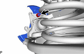
Remove the nut and the rear disc brake dust cover sub-assembly LH from the rear axle carrier.
-
-
REMOVE REAR SUSPENSION ARM COVER LH
-
REMOVE REAR HEIGHT CONTROL SENSOR SUB-ASSEMBLY LH
-
DISCONNECT REAR NO. 1 SHOCK ABSORBER BRACKET LH
-
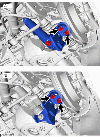
*A w/o AVS *B w/ AVS Remove the 2 bolts and disconnect the rear shock absorber bracket LH from the rear axle carrier.
-
-
DISCONNECT REAR NO. 1 SUSPENSION ARM ASSEMBLY LH
-
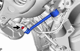
Remove the nut from the axle carrier.
-
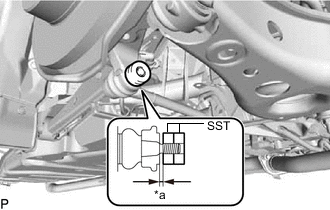
*a 1 mm (0.0394 in.) Install SST to the rear No. 1 suspension arm as shown in the illustration.
- SST
- 09960-20010 ( 09961-02060 )
Note
Make sure that the clearance measurement between SST and the rear axle assembly is 1 mm (0.0394 in.).
Tech Tips
Use 2 SST of the same type.
-
Using SST, disconnect the rear No. 1 suspension arm from the rear axle carrier as shown in the illustration.
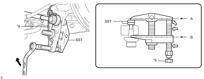
*a Tie the string without any slack. *b Place a wrench here. 
Turn 
Molybdenum Grease Application Area - SST
- 09960-20010 ( 09961-02010 )
CAUTION:
Apply molybdenum grease to the threads and end of SST bolt.
Note
-
Be sure to tighten the string firmly to secure SST to the rear axle assembly to prevent SST from falling off.
-
Install SST so that A and B are parallel.
-
Be sure to place a wrench on the part indicated in the illustration.
-
Do not damage the ball joint dust cover.
-
-
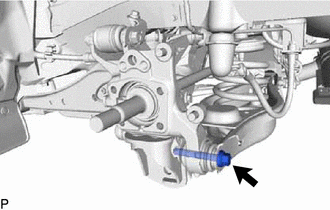
DISCONNECT REAR TRAILING ARM ASSEMBLY
-
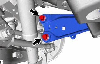
Remove the 2 bolts and disconnect the rear trailing arm from the rear axle carrier.
-
-
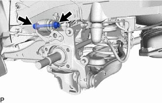
DISCONNECT REAR NO. 2 SUSPENSION ARM ASSEMBLY LH
-
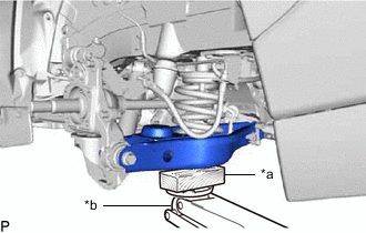
*a Wooden Block *b Jack Support the rear No. 2 suspension arm with a jack using a wooden block to avoid damage.
Note
Do not excessively jack up the rear No. 2 suspension arm assembly LH.
Tech Tips
Support the rear shock absorber at a position where it compresses by approximately 20 to 30 mm (0.788 to 1.181 in.).
-
Loosen the bolt and nut of the rear No. 2 suspension arm on the rear suspension member side.
-
Remove the bolt and disconnect the No. 2 rear suspension arm from the rear axle carrier.
-
Lower the jack gradually to remove the rear coil spring together with the rear upper coil spring insulator.
-
Remove the rear lower coil spring insulator from the rear No. 2 suspension arm.
-
-
REMOVE REAR AXLE CARRIER SUB-ASSEMBLY LH
-
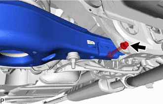
Remove the bolt and parking brake wire bracket and disconnect the rear upper control arm from the rear axle carrier.
Note
Since a stopper nut is used, remove the bolt.
-