DYNAMIC TORQUE CONTROL AWD SYSTEM, Diagnostic DTC:C1337/91

| DTC Code | DTC Name |
|---|---|
| C1337/91 | Diameter of the Tire is not Uniform |
DESCRIPTION
The 4WD ECU assembly outputs this DTC if a difference in tire size is detected.
| DTC No. | Detection Item | DTC Detection Condition | Trouble Area |
|---|---|---|---|
| C1337/91 | Diameter of the Tire is not Uniform | When the following continues for 36 seconds or more: At a vehicle speed of 30 km/h (18.6 mph) or more, the average speed difference between the front wheel and rear wheel is 4% or more. |
|
WIRING DIAGRAM
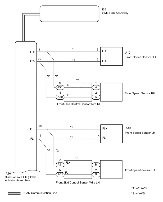
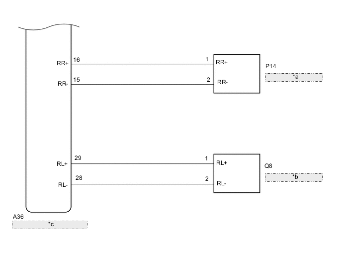
| *a | Rear Speed Sensor RH |
| *b | Rear Speed Sensor LH |
| *c | Skid Control ECU (Brake Actuator Assembly) |
CAUTION / NOTICE / HINT
Note
When the 4WD ECU assembly is replaced with a normal one from another vehicle, it is necessary to perform calibration.
PROCEDURE
-
CHECK TIRE CONDITION
-
Check the size and condition of all 4 tires.
Tech Tips
This DTC is output when tire deformation or a difference in tire size is detected.
OK The diameter and air pressure of all 4 tires are the same. Result Proceed to OK NG
NG 
REPLACE PERFORM AIR PRESSURE ADJUSTMENT OR REPLACE TIRES SO THAT ALL 4 TIRES ARE SAME IN SIZE Click here
OK 
-
-
CHECK FOR DTC
-
Clear the DTCs.
Chassis > Four Wheel Drive > Clear DTCs -
Start the engine.
-
Drive the vehicle at a speed of 30 km/h (19 mph) or more so that the same DTC is output.
Chassis > Four Wheel Drive > Trouble Codes -
Check if the speed sensor DTC (brake control system DTC) is output.
Chassis > ABS/VSC/TRC > Trouble Codes -
Read the DTCs using the GTS.
Result Result Proceed to Only DTC C1377/91 is output (w/o AVS) A Only DTC C1377/91 is output (w/ AVS) B DTC is not output C Speed sensor DTC (brake control system DTC) is output D
B 
INSPECT FRONT SKID CONTROL SENSOR WIRE Click here
C
CHECK FOR INTERMITTENT PROBLEMS Click here
D
REPAIR CIRCUIT INDICATED BY OUTPUT CODE (BRAKE CONTROL SYSTEM) Click here
A
-
-
CHECK HARNESS AND CONNECTOR (SPEED SENSOR - BRAKE ACTUATOR ASSEMBLY)
-
Turn the engine switch off.
-
Disconnect the A36 skid control ECU (brake actuator assembly) connector.
-
Disconnect the A12, A13, P14 and/or Q8 speed sensor connector(s).
-
Measure the resistance according to the value(s) in the table below.
Standard Resistance for Front RH: Tester Connection Condition Specified Condition A36-31 (FR+) - A12-6 (FR+) Always Below 1 Ω A36-30 (FR-) - A12-5 (FR-) Always A36-31 (FR+) or A12-6 (FR+) - Body ground and other terminals Always 10 kΩ or higher A36-30 (FR-) or A12-5 (FR-) - Body ground and other terminals Always for Front LH: Tester Connection Condition Specified Condition A36-18 (FL+) - A13-6 (FL+) Always Below 1 Ω A36-17 (FL-) - A13-5 (FL-) Always A36-18 (FL+) or A13-6 (FL+) - Body ground and other terminals Always 10 kΩ or higher A36-17 (FL-) or A13-5 (FL-) - Body ground and other terminals Always for Rear RH: Tester Connection Condition Specified Condition A36-16 (RR+) - P14-1 (RR+) Always Below 1 Ω A36-15 (RR-) - P14-2 (RR-) Always A36-16 (RR+) or P14-1 (RR+) - Body ground and other terminals Always 10 kΩ or higher A36-15 (RR-) or P14-2 (RR-) - Body ground and other terminals Always for Rear LH: Tester Connection Condition Specified Condition A36-29 (RL+) - Q8-1 (RL+) Always Below 1 Ω A36-28 (RL-) - Q8-2 (RL-) Always A36-29 (RL+) or Q8-1 (RL+) - Body ground and other terminals Always 10 kΩ or higher A36-28 (RL-) or Q8-2 (RL-) - Body ground and other terminals Always Result Proceed to OK NG
OK
GO TO STEP 6 Click here
NG
REPAIR OR REPLACE HARNESS OR CONNECTOR
-
-
INSPECT FRONT SKID CONTROL SENSOR WIRE
-
Make sure that there is no looseness at the locking part and the connecting part of the connectors.
-
Turn the engine switch off.
-
Disconnect the A50 and/or A51 front skid control sensor wire connector(s).
-
Disconnect the A and/or B front skid control sensor wire connector(s).
-
Measure the resistance according to the value(s) in the table below.
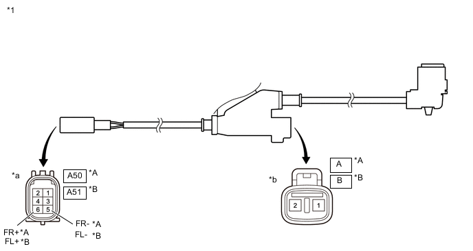
*A for RH *B for LH *1 Front Skid Control Sensor Wire - - *a Front view of wire harness connector
(to Vehicle Side Connector)
*b Front view of wire harness connector
(to Front Speed Sensor Side Connector)
Standard Resistance for RH: Tester Connection Condition Specified Condition A-1 - A50-6 (FR+) Always Below 1 Ω A-2 - A50-5 (FR-) Always A-1 or A50-6 (FR+) - Body ground and other terminals Always 10 kΩ or higher A-2 or A50-5 (FR-) - Body ground and other terminals Always for LH: Tester Connection Condition SpecifiedCondition B-1 - A51-6 (FL+) Always Below 1 Ω B-2 - A51-5 (FL-) Always B-1 or A51-6 (FL+) - Body ground and other terminals Always 10 kΩ or higher B-2 or A51-5 (FL-) - Body ground and other terminals Always Result Proceed to OK NG
NG
REPLACE FRONT SKID CONTROL SENSOR WIRE
OK
-
-
CHECK HARNESS AND CONNECTOR (SPEED SENSOR - BRAKE ACTUATOR ASSEMBLY)
-
Make sure that there is no looseness at the locking part and the connecting part of the connectors.
-
Reconnect the A50 and/or A51 front skid control sensor wire connector(s).
-
Disconnect the A36 skid control ECU (brake actuator assembly) connector.
-
Disconnect the P14 and/or Q8 speed sensor connector(s).
-
Measure the resistance according to the value(s) in the table below.
Standard Resistance for Front RH: Tester Connection Condition Specified Condition A36-31 (FR+) - A-1 Always Below 1 Ω A36-30 (FR-) - A-2 Always A36-31 (FR+) or A-1 - Body ground and other terminals Always 10 kΩ or higher A36-30 (FR-) or A-2 - Body ground and other terminals Always for Front LH: Tester Connection Condition Specified Condition A36-18 (FL+) - B-1 Always Below 1 Ω A36-17 (FL-) - B-2 Always A36-18 (FL+) or B-1 - Body ground and other terminals Always 10 kΩ or higher A36-17 (FL-) or B-2 - Body ground and other terminals Always for Rear RH: Tester Connection Condition Specified Condition A36-16(RR+) - P14-1(RR+) Always Below 1 Ω A36-15 (RR-) - P14-2 (RR-) Always A36-16 (RR+) or P14-1 (RR+) - Body ground and other terminals Always 10 kΩ or higher A36-15 (RR-) or P14-2 (RR-) - Body ground and other terminals Always for Rear LH: Tester Connection Condition Specified Condition A36-29 (RL+) - Q8-1 (RL+) Always Below 1 Ω A36-28 (RL-) - Q8-2 (RL-) Always A36-29 (RL+) or Q8-1 (RL+) - Body ground and other terminals Always 10 kΩ or higher A36-28 (RL-) or Q8-2 (RL-) - Body ground and other terminals Always Result Proceed to OK NG
NG
REPAIR OR REPLACE HARNESS OR CONNECTOR
OK
-
-
PERFORM TEST MODE (SIGNAL CHECK)
-
Turn the engine switch off.
-
Perform the sensor check in the Test Mode procedure.
Chassis > ABS/VSC/TRC > UtilityTester Display Signal Check OK All Test Mode (signal check) inspection items are normal. Result Proceed to OK NG
NG
CHECK SPEED SENSOR ROTOR Click here
OK
-
-
RECONFIRM DTC
-
Clear the DTCs.
Chassis > Four Wheel Drive > Clear DTCs -
Start the engine.
-
Drive the vehicle at a speed of 30 km/h (19 mph) or more and check that the same DTC is output.
Chassis > Four Wheel Drive > Trouble CodesResult Proceed to DTC is output DTC is not output
DTC is output
REPLACE BRAKE ACTUATOR ASSEMBLY Click here
DTC is not output
CHECK FOR INTERMITTENT PROBLEMS Click here
-
-
CHECK SPEED SENSOR ROTOR
-
Turn the engine switch off.
-
Remove the front speed sensor rotor (front axle hub sub-assembly) or rear speed sensor rotor (rear axle hub and bearing assembly).
for Front: Click here
for Rear: Click here
-
Check the speed sensor rotor.
OK No scratches, oil, or foreign matter on the rotors. Tech Tips
-
If the front speed sensor rotor needs to be replaced, replace it together with the front axle hub sub-assembly.
-
If the rear speed sensor rotor needs to be replaced, replace it together with the rear axle hub and bearing assembly.
Result Proceed to OK NG -
NG
CLEAN OR REPLACE SPEED SENSOR ROTOR
OK
-
-
REPLACE SPEED SENSOR
-
Turn the engine switch off.
-
Replace the front speed sensor or the rear speed sensor.
for Front: Click here
for Rear: Click here
Result Proceed to NEXT
NEXT
-
-
RECONFIRM DTC
-
Clear the DTCs.
Chassis > Four Wheel Drive > Clear DTCs -
Start the engine.
-
Drive the vehicle at a speed of 30 km/h (19 mph) or more and check that the same DTC is output.
Chassis > Four Wheel Drive > Trouble CodesResult Proceed to DTC is output DTC is not output Tech Tips
Reinstall the sensor, connectors, etc. and restore the vehicle to its prior condition before rechecking DTCs.
DTC is not output
END
DTC is output
-
-
REPLACE BRAKE ACTUATOR ASSEMBLY
-
Replace the skid control ECU (brake actuator assembly).
Result Proceed to NEXT
NEXT
-
-
RECONFIRM DTC
-
Clear the DTCs.
Chassis > Four Wheel Drive > Clear DTCs -
Start the engine.
-
Drive the vehicle at a speed of 30 km/h (19 mph) or more and check that the same DTC is output.
Chassis > Four Wheel Drive > Trouble CodesResult Proceed to DTC is output DTC is not output
DTC is output
REPLACE 4WD ECU ASSEMBLY fro LHD: Click here
REPLACE 4WD ECU ASSEMBLY for RHD: Click hereDTC is not output
END
-