DYNAMIC TORQUE CONTROL AWD SYSTEM, Diagnostic DTC:C1298/98

| DTC Code | DTC Name |
|---|---|
| C1298/98 | Linear Solenoid Circuit |
DESCRIPTION
The 4WD ECU assembly receives signals from each sensor to control clutch fluid pressure for limiting the center differential operation, which distributes torque according to the driving conditions.
| DTC No. | Detection Item | DTC Detection Condition | Trouble Area |
|---|---|---|---|
| C1298/98 | Linear Solenoid Circuit | When all of the following continue for 1 second or more:
|
|
WIRING DIAGRAM
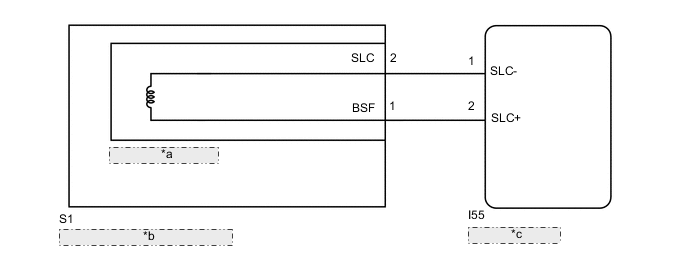
| *a | 4WD Linear Solenoid |
| *b | Transmission Coupling Assembly |
| *c | 4WD ECU Assembly |
CAUTION / NOTICE / HINT
Note
When the 4WD ECU assembly is replaced with a normal one from another vehicle, it is necessary to perform calibration.
PROCEDURE
-
CHECK HARNESS AND CONNECTOR (4WD ECU ASSEMBLY - TRANSMISSION COUPLING ASSEMBLY)
-
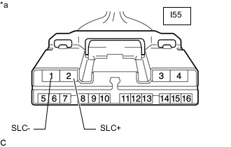
*a Front view of wire harness connector
(to 4WD ECU Assembly)
Disconnect the I55 4WD ECU assembly connector.
-
Measure the resistance according to the value(s) in the table below.
Standard Resistance Tester Connection Condition Specified Condition I55-2 (SLC+) - I55-1 (SLC-) 20°C (68°F) 2.2 to 2.6 Ω I55-2 (SLC+) - Body ground Always 10 kΩ or higher I55-1 (SLC-) - Body ground Always 10 kΩ or higher Result Proceed to OK NG
OK 
REPLACE 4WD ECU ASSEMBLY for LHD: Click here
REPLACE 4WD ECU ASSEMBLY for RHD: Click hereNG 
-
-
INSPECT TRANSMISSION COUPLING ASSEMBLY
-
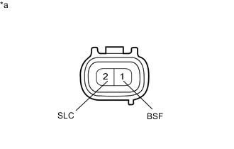
*a Component without harness connected
(4WD Linear Solenoid (Transmission Coupling Assembly))
Disconnect the S1 4WD linear solenoid (transmission coupling assembly) connector.
-
Measure the resistance according to the value(s) in the table below.
Standard Resistance Tester Connection Condition Specified Condition 1 (BSF) - 2 (SLC) 20°C (68°F) 2.2 to 2.6 Ω 1 (BSF) - Body ground Always 10 kΩ or higher 2 (SLC) - Body ground Always 10 kΩ or higher Result Proceed to OK NG
OK
REPAIR OR REPLACE HARNESS OR CONNECTOR
NG
REPLACE TRANSMISSION COUPLING ASSEMBLY Click here
-