AUTOMATIC TRANSAXLE SYSTEM, Diagnostic DTC:P275613

| DTC Code | DTC Name |
|---|---|
| P275613 | Torque Converter Clutch Pressure Control Solenoid Control Circuit Open |
DESCRIPTION
Refer to the system description for DTC P27567F.
| DTC No. | Detection Item | DTC Detection Condition | Trouble Area | MIL | Memory | Note |
|---|---|---|---|---|---|---|
| P275613 | Torque Converter Clutch Pressure Control Solenoid Control Circuit Open | Open or short is detected in shift solenoid valve SLU circuit for 1 sec. or more while driving (1-trip detection logic) |
|
Comes on | DTC stored | SAE: P2759 |
MONITOR DESCRIPTION
When an open or short in the shift solenoid valve SLU circuit is detected, the ECM determines there is a malfunction. The ECM will illuminate the MIL and store this DTC.
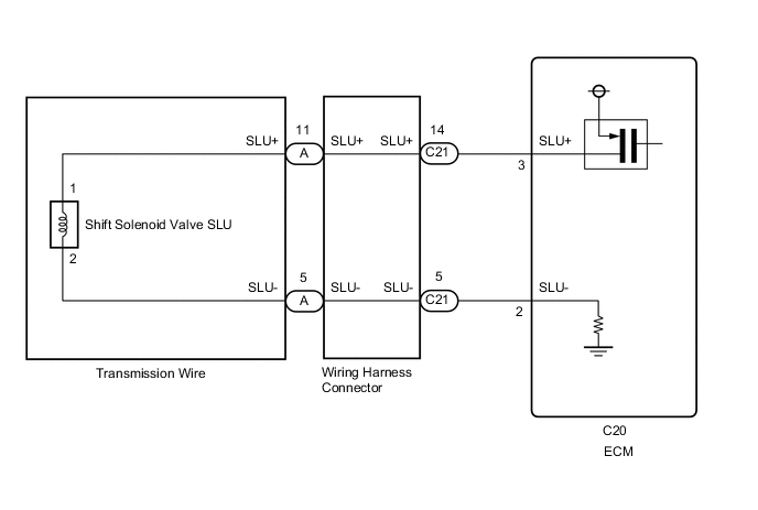
WIRING DIAGRAM
CAUTION / NOTICE / HINT
Note
Perform registration and/or initialization when parts related to the automatic transaxle are replaced.
PROCEDURE
-
CHECK HARNESS AND CONNECTOR (SHIFT SOLENOID VALVE SLU CIRCUIT)
-
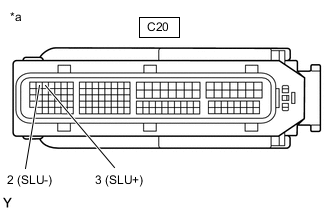
*a Front view of wire harness connector
(to ECM)
Disconnect the ECM connector.
-
Measure the resistance according to the value(s) in the table below.
Standard Resistance Tester Connection Condition Specified Condition C20-3 (SLU+) - C20-2 (SLU-) 20°C (68°F) 5.0 to 5.6 Ω C20-3 (SLU+) - Body ground and other terminals Always 10 kΩ or higher C20-2 (SLU-) - Body ground and other terminals Always 10 kΩ or higher Result Proceed to OK NG
OK 
REPLACE ECM Click here
NG 
-
-
CHECK HARNESS AND CONNECTOR (WIRING HARNESS CONNECTOR - ECM)
-
Disconnect the C21 wiring harness connector.
-
Disconnect the C20 ECM connector.
-
Measure the resistance according to the value(s) in the table below.
Standard Resistance Tester Connection Condition Specified Condition C21-14 (SLU+) - C20-3 (SLU+) Always Below 1 Ω C21-5 (SLU-) - C20-2 (SLU-) Always Below 1 Ω C21-14 (SLU+) or C20-3 (SLU+) - Body ground and other terminals Always 10 kΩ or higher C21-5 (SLU-) or C20-2 (SLU-) - Body ground and other terminals Always 10 kΩ or higher Result Proceed to OK NG
NG
REPAIR OR REPLACE HARNESS OR CONNECTOR
OK
-
-
INSPECT TRANSMISSION WIRE (SHIFT SOLENOID VALVE SLU)
-
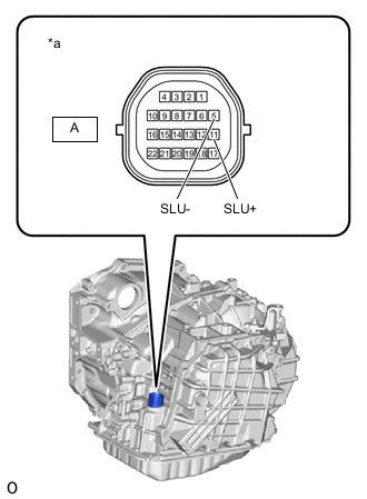
*a Component without harness connected
(Transmission Wire)
Remove the wiring harness connector.
-
Measure the resistance according to the value(s) in the table below.
Standard Resistance Tester Connection Condition Specified Condition A-11 (SLU+) - A-5 (SLU-) 20°C (68°F) 5.0 to 5.6 Ω A-11 (SLU+) - Body ground and other terminals Always 10 kΩ or higher A-5 (SLU-) - Body ground and other terminals Always 10 kΩ or higher Result Proceed to OK NG
OK
REPLACE WIRING HARNESS CONNECTOR Click here
NG
-
-
INSPECT SHIFT SOLENOID VALVE SLU
-
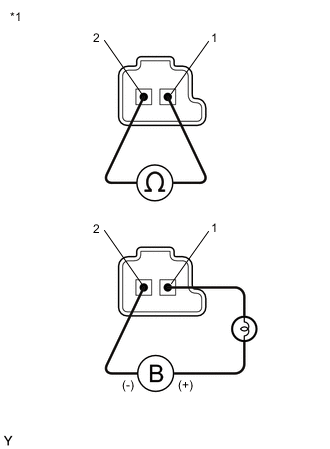
*1 Shift Solenoid Valve SLU Remove shift solenoid valve SLU.
-
Measure the resistance according to the value(s) in the table below.
Standard Resistance Tester Connection Condition Specified Condition 1 - 2 20°C (68°F) 5.0 to 5.6 Ω -
Apply 12 V battery voltage to the shift solenoid valve and check that the valve moves and makes an operating noise.
OK Measurement Condition Specified Condition
-
Battery positive (+) with a 21 W bulb → Terminal 1
-
Battery negative (-) → Terminal 2
Valve moves and makes an operating noise Result Proceed to OK NG -
OK
REPLACE TRANSMISSION WIRE Click here
NG
REPLACE SHIFT SOLENOID VALVE SLU Click here
-