AUTOMATIC TRANSAXLE SYSTEM, Diagnostic DTC:P098712

| DTC Code | DTC Name |
|---|---|
| P098712 | Transmission Fluid Pressure Sensor/Switch "E" Circuit Short to Battery |
DESCRIPTION
No. 3 ATF pressure switch is installed in the lock-up solenoid ATF output passage and is used to detect a malfunction in the lock-up solenoid.
| DTC No. | Detection Item | DTC Detection Condition | Trouble Area | MIL | Memory | Note |
|---|---|---|---|---|---|---|
| P098712 | Transmission Fluid Pressure Sensor/Switch "E" Circuit Short to Battery | Both conditions are met (2-trip detection logic):
|
|
Comes on | DTC stored | SAE: P0990 |
MONITOR DESCRIPTION
The ECM illuminates the MIL and stores the DTC if it detects that the ATF pressure switch is OFF with the lock-up solenoid ON or if it detects that the ATF pressure switch is ON with the lock-up solenoid OFF.
CAUTION / NOTICE / HINT
Note
Perform registration and/or initialization when parts related to the automatic transaxle are replaced.
PROCEDURE
-
CHECK OTHER DTC OUTPUT (IN ADDITION TO DTC P098712)
-
Connect the GTS to the DLC3.
-
Turn the engine switch on (IG).
-
Turn the GTS on.
-
Enter the following menus: Powertrain / Transmission / Trouble Codes.
Powertrain > Transmission > Trouble Codes -
Read the DTCs using the GTS.
Result Result Proceed to Only DTC P098712 is output A P098712 and other DTCs are output B Tech Tips
If a solenoid is stuck OFF, DTCs for several solenoids including the malfunctioning solenoid will be stored.
B 
GO TO DTC CHART Click here
A 
-
-
CHECK HARNESS AND CONNECTOR (NO. 3 ATF PRESSURE SWITCH CIRCUIT)
-
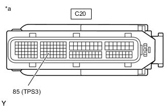
*a Front view of wire harness connector
(to ECM)
Disconnect the ECM connector.
-
Measure the resistance according to the value(s) in the table below.
Standard Resistance Tester Connection Condition Specified Condition C20-85 (TPS3) - Body ground Always 10 kΩ or higher Result Proceed to OK NG
OK
REPLACE ECM Click here
NG
-
-
CHECK HARNESS AND CONNECTOR (WIRING HARNESS CONNECTOR - ECM)
-
Disconnect the C21 wiring harness connector.
-
Disconnect the C20 ECM connector.
-
Measure the resistance according to the value(s) in the table below.
Standard Resistance Tester Connection Condition Specified Condition C21-10 (TPS3) or C20-85 (TPS3) - Body ground and other terminals Always 10 kΩ or higher Result Proceed to OK NG
NG
REPAIR OR REPLACE HARNESS OR CONNECTOR
OK
-
-
INSPECT TRANSMISSION WIRE
-
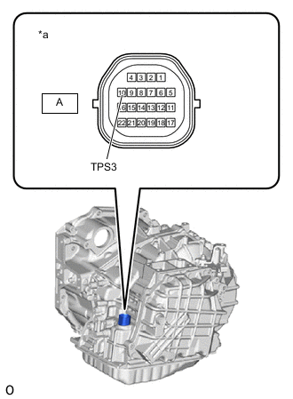
*a Component without harness connected
(Transmission Wire)
Remove the wiring harness connector.
-
Measure the resistance according to the value(s) in the table below.
Standard Resistance Tester Connection Condition Specified Condition A-10 (TPS3) - Body ground and other terminals Always 10 kΩ or higher Result Proceed to OK NG
OK
REPLACE WIRING HARNESS CONNECTOR Click here
NG
-
-
INSPECT NO. 3 ATF PRESSURE SWITCH (ATF TEMPERATURE SENSOR ASSEMBLY)
-
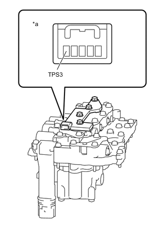
*a Component without harness connected
(ATF Temperature Sensor Assembly)
Disconnect the No. 3 ATF pressure switch connector.
-
Measure the resistance according to the value(s) in the table below.
Standard Resistance Tester Connection Condition Specified Condition TPS3 - Body ground and other terminals Always 10 kΩ or higher Result Proceed to OK NG
OK
REPLACE TRANSMISSION WIRE Click here
NG
REPLACE NO. 3 ATF PRESSURE SWITCH (ATF TEMPERATURE SENSOR ASSEMBLY) Click here
-