AUTOMATIC TRANSAXLE SYSTEM, Diagnostic DTC:P074011

| DTC Code | DTC Name |
|---|---|
| P074011 | Torque Converter Clutch Circuit Short to Ground |
DESCRIPTION
Shift solenoid valve SL is turned on and off by signals from the ECM to control the hydraulic pressure acting on the lock-up relay valve, which then controls operation of the lock-up clutch.
| DTC No. | Detection Item | DTC Detection Condition | Trouble Area | MIL | Memory | Note |
|---|---|---|---|---|---|---|
| P074011 | Torque Converter Clutch Circuit Short to Ground | The shift solenoid valve SL terminal voltage level is low, when the shift solenoid valve SL is operated (2 trip detection logic). |
|
Comes on | DTC stored | SAE: P2769 |
Fail-safe function:
If the ECM detects a malfunction, it turns shift solenoid valve SL off.
MONITOR DESCRIPTION
Based on the signals from the throttle position sensor, the air flow meter and the crankshaft position sensor, the ECM sends a signal to the shift solenoid valve SL to regulate the hydraulic pressure and provide smoother torque converter clutch engagement. The shift solenoid valve SL responds to commands from the ECM. The valve controls the lock-up relay valve to perform the torque-converter lock-up function. If the ECM detects an open or short in the shift solenoid valve SL circuit, it will illuminate the MIL and store a DTC.
WIRING DIAGRAM
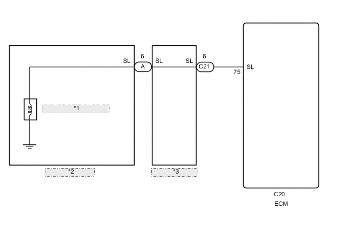
| *1 | Shift Solenoid Valve SL |
| *2 | Transmission Wire |
| *3 | Wiring Harness Connector |
CAUTION / NOTICE / HINT
Note
Perform registration and/or initialization when parts related to the automatic transaxle are replaced.
PROCEDURE
-
CHECK HARNESS AND CONNECTOR (SHIFT SOLENOID VALVE SL CIRCUIT)
-
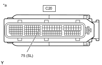
*a Front view of wire harness connector
(to ECM)
Disconnect the ECM connector.
-
Measure the resistance according to the value(s) in the table below.
Standard Resistance Tester Connection Condition Specified Condition C20-75 (SL) - Body ground 20°C (68°F) 11 to 15 Ω Result Proceed to OK NG
OK 
REPLACE ECM Click here
NG 
-
-
CHECK HARNESS AND CONNECTOR (WIRING HARNESS CONNECTOR - ECM)
-
Disconnect the C21 wiring harness connector.
-
Disconnect the C20 ECM connector.
-
Measure the resistance according to the value(s) in the table below.
Standard Resistance Tester Connection Condition Specified Condition C21-6 (SL) or C20-75 (SL) - Body ground and other terminals Always 10 kΩ or higher Result Proceed to OK NG
NG
REPAIR OR REPLACE HARNESS OR CONNECTOR
OK
-
-
INSPECT TRANSMISSION WIRE (SHIFT SOLENOID VALVE SL)
-
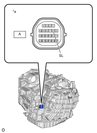
*a Component without harness connected
(Transmission Wire)
Remove the wiring harness connector.
-
Measure the resistance according to the value(s) in the table below.
Standard Resistance Tester Connection Condition Specified Condition A-6 (SL) - Body ground 20°C (68°F) 11 to 15 Ω Result Proceed to OK NG
OK
REPLACE WIRING HARNESS CONNECTOR Click here
NG
-
-
INSPECT SHIFT SOLENOID VALVE SL
-
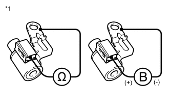
*1 Shift Solenoid Valve SL Remove shift solenoid valve SL.
-
Measure the resistance according to the value(s) in the table below.
Standard Resistance Tester Connection Condition Specified Condition Shift solenoid valve SL connector terminal - Shift solenoid valve SL body 20°C (68°F) 11 to 15 Ω -
Apply 12 V battery voltage to the shift solenoid valve and check that the valve moves and makes an operating noise.
OK Measurement Condition Specified Condition
-
Battery positive (+) → Shift solenoid valve SL connector
-
Battery negative (-) → Shift solenoid valve SL body
Valve moves and makes an operating noise Result Proceed to OK NG -
OK
REPLACE TRANSMISSION WIRE Click here
NG
REPLACE SHIFT SOLENOID VALVE SL Click here
-