AUTOMATIC TRANSAXLE SYSTEM TERMINALS OF ECU

-
ECM
Tech Tips
The standard voltage between each pair of ECM terminals is shown in the table below.
In the table, first follow the information under "Condition". Look under "Terminal No. (Symbol)" for the terminals to be inspected. The standard voltage between the terminals is shown under "Specified Condition".
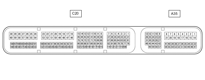
Use the illustration below as a reference for the ECM terminals.
Terminal No. (Symbol) Wiring Color Terminal Description Condition Specified Condition C20-1 (SLT+) - C20-31 (SLT-) R - V Shift solenoid valve SLT signal Engine idling Pulse generation C20-3 (SLU+) - C20-2 (SLU-) W - B Shift solenoid valve SLU signal 2nd, 3rd, 4th, 5th or 6th gear
(Flex lock-up on)
Pulse generation C20-5 (SL2+) - C20-4 (SL2-) GR - L Shift solenoid valve SL2 signal 4th, 5th or 6th gear Pulse generation C20-7 (SL3+) - C20-6 (SL3-) G - R Shift solenoid valve SL3 signal 2nd or 6th gear Pulse generation C20-13 (SL4+) - C20-12 (SL4-) W - B Shift solenoid valve SL4 signal 3rd or 5th gear Pulse generation C20-15 (SL1+) - C20-14 (SL1-) P - LG Shift solenoid valve SL1 signal 1st, 2nd, 3rd or 4th gear Pulse generation C20-34 (D) - C20-53 (E1) B - W-B D shift position switch signal Engine switch on (IG) and shift lever in D, M, "+" or "-" 11 to 14 V Engine switch on (IG) and shift lever not in D, M, "+" or "-" Below 1 V C20-35 (R) - C20-53 (E1) W - W-B R shift position switch signal Engine switch on (IG) and shift lever in R 11 to 14 V Engine switch on (IG) and shift lever not in R Below 1 V C20-64 (P) - C20-53 (E1) L - W-B P shift position switch signal Engine switch on (IG) and shift lever in P 11 to 14 V Engine switch on (IG) and shift lever not in P Below 1 V C20-65 (N) - C20-53 (E1) R - W-B N shift position switch signal Engine switch on (IG) and shift lever in N 11 to 14 V Engine switch on (IG) and shift lever not in N Below 1 V C20-71 (NTB) - C20-53 (E1) W - W-B Power source for sensor (fixed voltage) Engine switch on (IG) 11 to 14 V C20-72 (NTO) - C20-53 (E1) B - W-B Speed sensor (NT) signal Engine idling Pulse generation C20-73 (NCB) - C20-53 (E1) W - W-B Power source for sensor (fixed voltage) Engine switch on (IG) 11 to 14 V C20-74 (NCO) - C20-53 (E1) R - W-B Speed sensor (NC) signal Vehicle driving Pulse generation C20-75 (SL) - C20-53 (E1) R - W-B Shift solenoid valve SL signal All gears 11 to 14 V C20-84 (THO1) - C20-83 (ETHO) L - G ATF temperature sensor signal ATF temperature: 115°C (239°F) or higher Below 1.5 V C20-85 (TPS3) - C20-53 (E1) GR - W-B No. 3 ATF pressure switch signal Lock-up operating Below 1 V Lock-up not operating 11 to 14 V A35-1 (BATT) - C20-53 (E1) L - W-B Battery (for measuring battery voltage and for ECM memory) Always 11 to 14 V A35-9 (STP) - C20-53 (E1) L - W-B Stop light switch assembly signal Brake pedal depressed 7.5 to 14 V Brake pedal released 0 to 1.5 V A35-29 (STA) - C20-53 (E1) L - W-B Starter assembly signal Cranking 6 V or higher A35-36 (PWMS) - C20-53 (E1) GR - W-B Pattern select switch (SPORT) signal Engine switch on (IG) and pattern select switch being turned and held at SPORT position Below 1.5 V Engine switch on (IG) and pattern select switch not turned 11 to 14 V A35-39 (SPCN) - C20-53 (E1) P - W-B Pattern select switch (NORMAL) signal Engine switch on (IG) and pattern select switch being pushed and held at NORMAL position Below 1.5 V Engine switch on (IG) and pattern select switch not pushed 11 to 14 V A35-41 (ECCS) - Body ground L - Body ground Earth (ground) circuit of ECM Always Below 1 Ω A35-42 (SFTU) - C20-53 (E1) LG - W-B Up shift switch signal Engine switch on (IG) and shift lever in M 11 to 14 V Engine switch on (IG) and shift lever in "+" (Up shift) Below 1 V Engine switch on (IG) and "+" shift paddle operated (up-shift)* Below 1 V A35-43 (SFTD) - C20-53 (E1) GR - W-B Down shift switch signal Engine switch on (IG) and shift lever in M 11 to 14 V Engine switch on (IG) and shift lever in "-" (Down shift) Below 1 V Engine switch on (IG) and "-" shift paddle operated (down-shift)* Below 1 V A35-44 (SPD) - C20-53 (E1) Y - W-B Vehicle speed signal from combination meter assembly signal Vehicle driving Pulse generation A35-57 (NSW) - C20-53 (E1) W - W-B Park/neutral switch signal Engine switch on (IG) and shift lever in P or N Below 3 V Engine switch on (IG) and shift lever not in P or N 11 to 14 V A35-59 (S) - C20-53 (E1) B - W-B M shift position switch signal Engine switch on (IG) and shift lever in M, "+" or "-" 11 to 14 V Engine switch on (IG) and shift lever not in M, "+" or "-" Below 1 V
-
*: w/ Shift Paddle Switch
-