STOP AND START SYSTEM Neutral Position Switch Circuit
DESCRIPTION
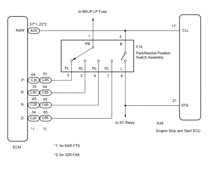
The engine stop and start ECU uses the park/neutral position switch assembly installed to the automatic transaxle assembly*1 or continuously variable transaxle assembly*2 to detect when the shift lever is in P or N.
-
*1: for 8AR-FTS
-
*2: for 3ZR-FAE
WIRING DIAGRAM
PROCEDURE
-
READ VALUE USING GTS (NEUTRAL SWITCH)
-
Connect the GTS to the DLC3.
-
Turn the engine switch on (IG).
-
Turn the GTS on.
-
Enter the following menus: Powertrain / Stop and Start / Data List / Neutral Switch.
-
In accordance with the display on the GTS, read the Data List.
Powertrain > Stop and Start > Data ListTester Display Neutral Switch OK Tester Display Condition Normal Condition Neutral Switch Shift lever in P or N ON Shift lever not in P or N OFF Result Proceed to OK NG
OK 
GO TO PROCEED TO NEXT SUSPECTED AREA SHOWN IN PROBLEM SYMPTOMS TABLE Click here
NG 
-
-
INSPECT PARK/NEUTRAL POSITION SWITCH ASSEMBLY
-
Inspect the park/neutral position switch assembly.
-
for U661E:
-
for U661F:
-
for K114:
-
for K114F:
Result Proceed to OK NG -
NG
REPLACE PARK/NEUTRAL POSITION SWITCH ASSEMBLY for U661E: Click here for U661F: Click here for K114: Click here for K114F: Click here
OK
-
-
CHECK HARNESS AND CONNECTOR (ENGINE STOP AND START ECU - PARK/NEUTRAL POSITION SWITCH ASSEMBLY)
-
Disconnect the A38 engine stop and start ECU connector.
-
Disconnect the C14 park/neutral position switch assembly connector.
-
Measure the resistance according to the value(s) in the table below.
Standard Resistance Tester Connection Condition Specified Condition A38-21 (STA) - C14-9 (L) Always Below 1 Ω A38-17 (CLL) - C14-4 (B) Always Below 1 Ω A38-21 (STA) - Body ground Always 80 to 180 Ω A38-17 (CLL) - Body ground Always 10 kΩ or higher C14-9 (L) - Body ground Always 80 to 180 Ω C14-4 (B) - Body ground Always 10 kΩ or higher Result Proceed to OK NG
OK
REPLACE ENGINE STOP AND START ECU Click here
NG
REPAIR OR REPLACE HARNESS OR CONNECTOR
-