РЫЧАГ ПЕРЕКЛЮЧЕНИЯ ПЕРЕДАЧ УСТАНОВКА

PROCEDURE
-
INSTALL SHIFT LEVER ASSEMBLY
-
Install the shift lever assembly to the No. 1 instrument panel brace sub-assembly with the 4 bolts.
- Torque:
- 12 N*m { 122 kgf*cm, 9 ft.*lbf }
-
Install the 3 screws.
-
Connect the shift lock control ECU connector.
-
Connect the transmission control switch connector.
-
-
CONNECT TRANSMISSION CONTROL CABLE ASSEMBLY
-
Turn the nut of the transmission control cable assembly approximately 180° counterclockwise. While holding the nut in place, push in the stopper until it clicks twice.
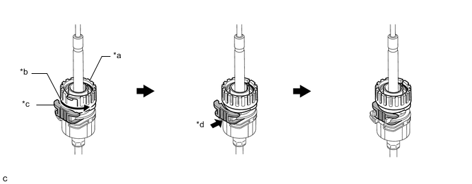
*a Nut *b Turn approximately 180° *c Stopper *d Push in Tech Tips
If the stopper cannot be pushed in, slightly turn the nut clockwise and then push in the stopper again.
-
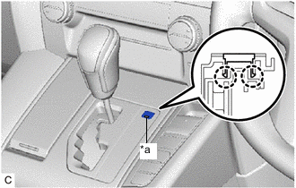
Connect the transmission control cable assembly to the shift lever assembly. Check that the spring is positioned at (A) and push in the stopper.
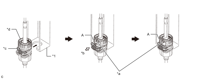
*1 Shift Lever Assembly - - *a Spring *b Push in *c Stopper *d Nut Note
-
If the stopper cannot be pushed in, slightly turn the nut clockwise and then push in the stopper again.
-
Make sure that the transmission control cable assembly is securely locked.
-
-
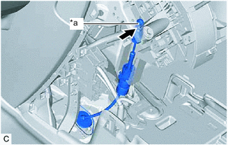
*a Pin Confirm that the shift lever is in N, and then connect the transmission control cable assembly to the shift lever assembly.
Note
Securely connect the transmission control cable assembly to the shift lever assembly.
-
-
INSPECT SHIFT LEVER POSITION
-
ADJUST SHIFT LEVER POSITION
-
INSTALL INSTRUMENT CLUSTER FINISH PANEL ASSEMBLY (for Separate Console Box Type)
-
INSTALL INSTRUMENT PANEL BOX ASSEMBLY (for Separate Console Box Type)
-
INSTALL LOWER CENTER INSTRUMENT CLUSTER FINISH PANEL SUB-ASSEMBLY
-
INSTALL COMBINATION SWITCH ASSEMBLY
-
INSTALL AIR CONDITIONING CONTROL ASSEMBLY
-
INSTALL CONSOLE BOX ASSEMBLY (for Integrated Type)
-
INSTALL SHIFT LEVER KNOB SUB-ASSEMBLY
-
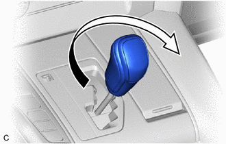
Turn the shift lever knob sub-assembly clockwise to install the shift lever knob sub-assembly.
-
-
INSTALL SHIFT LOCK RELEASE BUTTON COVER
-
*a Groove Engage the 2 claws to install the shift lock release button cover to the lower center instrument cluster finish panel sub-assembly.
Note
Install the shift lock release button cover with its groove facing the rear of the vehicle.
-