РЫЧАГ ПЕРЕКЛЮЧЕНИЯ ПЕРЕДАЧ СНЯТИЕ

PROCEDURE
-
SECURE VEHICLE
-
Fully apply the parking brake and chock a wheel.
CAUTION:
-
Make sure to apply the parking brake and chock a wheel before performing this procedure.
-
If the vehicle is not secure and the shift lever is moved to N, the vehicle may suddenly move, possibly resulting in an accident or serious injury.
-
-
-
REMOVE SHIFT LOCK RELEASE BUTTON COVER
-
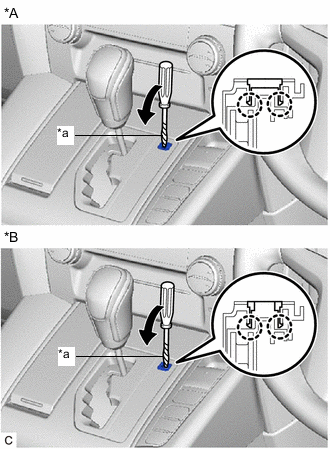
*A Type A *B Type B *a Protective Tape Using a screwdriver with its tip wrapped with protective tape, disengage the 2 claws to remove the shift lock release button cover from the lower center instrument cluster finish panel sub-assembly.
Note
Be careful not to damage the shift lock release button cover and lower center instrument cluster finish panel sub-assembly.
-
-
REMOVE SHIFT LEVER KNOB SUB-ASSEMBLY
-
Move the shift lever to N.
-
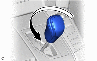
Turn the shift lever knob sub-assembly counterclockwise to remove the shift lever knob sub-assembly.
-
-
REMOVE CONSOLE BOX ASSEMBLY (for Integrated Type)
-
REMOVE AIR CONDITIONING CONTROL ASSEMBLY
-
REMOVE COMBINATION SWITCH ASSEMBLY
-
REMOVE LOWER CENTER INSTRUMENT CLUSTER FINISH PANEL SUB-ASSEMBLY
-
REMOVE INSTRUMENT PANEL BOX ASSEMBLY (for Separate Console Box Type)
-
REMOVE INSTRUMENT CLUSTER FINISH PANEL ASSEMBLY (for Separate Console Box Type)
-
DISCONNECT TRANSMISSION CONTROL CABLE ASSEMBLY
-
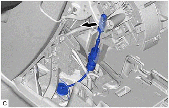
Disconnect the transmission control cable assembly from the shift lever assembly.
-
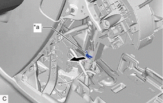
*a Stopper Using a screwdriver, pull out the stopper of the transmission control cable assembly.
Note
Do not remove the stopper. If it is removed, reinstall it to its original position.
-
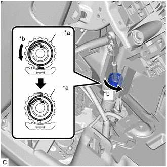
*a Nut *b Turn approximately 180° Turn the nut counterclockwise approximately 180° and, while holding the nut in that position, disconnect the transmission control cable assembly from the shift lever assembly.
Note
Do not turn the nut excessively as the internal spring may come off and transmission control cable assembly will not be reusable.
-
-
REMOVE SHIFT LEVER ASSEMBLY
-
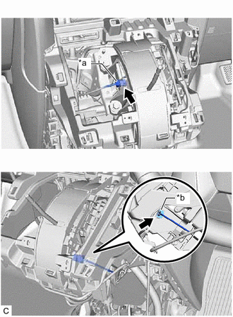
*a Shift Lock Control ECU Connector *b Transmission Control Switch Connector Disconnect the shift lock control ECU connector.
-
Disconnect the transmission control switch connector.
-
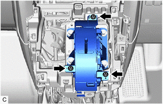
Remove the 3 screws.
-
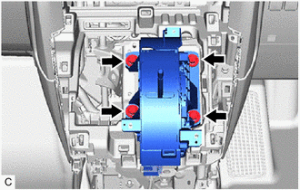
Remove the 4 bolts and shift lever assembly from No. 1 instrument panel brace sub-assembly.
-