ТРОС МЕХАНИЗМА ПЕРЕКЛЮЧЕНИЯ ПЕРЕДАЧ УСТАНОВКА

PROCEDURE
-
INSTALL TRANSMISSION CONTROL CABLE ASSEMBLY
-
Pass the transmission control cable assembly into the vehicle and connect the transmission control cable assembly to the vehicle body with the 2 bolts.
- Torque:
- 5.0 N*m { 51 kgf*cm, 44 in.*lbf }
-
Connect the transmission control cable assembly to vehicle body with the 2 nuts.
- Torque:
- 5.0 N*m { 51 kgf*cm, 44 in.*lbf }
-
Install the transmission control cable support to the transmission control cable assembly.
-
Connect the transmission control cable assembly with the transmission control cable support to the continuously variable transaxle assembly with the bolt.
- Torque:
- 5.0 N*m { 51 kgf*cm, 44 in.*lbf }
-
Connect the transmission control cable assembly to the No. 1 transmission control cable bracket with a new clip.
-
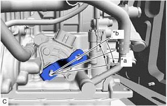
*a P Position *b N Position Turn the control shaft lever clockwise until it stops, then turn it counterclockwise 2 notches.
-
Connect the transmission control cable assembly to the control shaft lever with the nut.
- Torque:
- 12 N*m { 122 kgf*cm, 9 ft.*lbf }
-
Turn the nut of the transmission control cable assembly approximately 180° counterclockwise. While holding the nut in place, push in the stopper until it clicks twice.
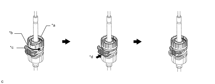
*a Nut *b Turn approximately 180° *c Stopper *d Push in Tech Tips
If the stopper cannot be pushed in, slightly turn the nut clockwise and then push in the stopper again.
-
Connect the transmission control cable assembly to the shift lever assembly. Check that the spring is positioned at (A) and push in the stopper.
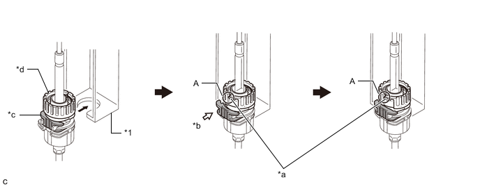
*1 Shift Lever Assembly - - *a Spring *b Push in *c Stopper *d Nut Note
-
If the stopper cannot be pushed in, slightly turn the nut clockwise and then push in the stopper again.
-
Make sure that the transmission control cable assembly is securely locked.
-
-
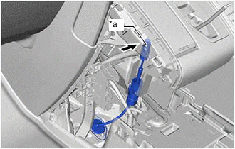
*a Pin Connect the transmission control cable assembly to the shift lever assembly.
Note
-
The shift lever should be in N.
-
Connect the transmission control cable assembly all the way to the base of the pin.
-
-
-
INSTALL CONSOLE BOX ASSEMBLY (for Integrated Type)
-
INSTALL INSTRUMENT CLUSTER FINISH PANEL ASSEMBLY (for Separate Console Box Type)
-
INSTALL INSTRUMENT PANEL BOX ASSEMBLY (for Separate Console Box Type)
-
INSTALL CENTER NO. 2 INSTRUMENT CLUSTER FINISH PANEL (for Separate Console Box Type)
-
INSTALL CENTER NO. 1 INSTRUMENT CLUSTER FINISH PANEL (for Separate Console Box Type)
-
INSTALL AIR CLEANER CASE SUB-ASSEMBLY
-
INSTALL AIR CLEANER CAP SUB-ASSEMBLY
-
INSTALL BATTERY CARRIER SUPPORT
-
INSTALL BATTERY CARRIER
-
INSTALL BATTERY
-
INSTALL CENTER NO. 1 COWL TOP VENTILATOR LOUVER
-
CONNECT CABLE TO NEGATIVE BATTERY TERMINAL
Note
When disconnecting the cable, some systems need to be initialized after the cable is reconnected.
-
PERFORM INITIALIZATION
-
INSPECT SHIFT LEVER POSITION
-
ADJUST SHIFT LEVER POSITION