PROCEDURE
- Click here
INSTALL RUBBER SEAL
-
Install the rubber seal to the starter drive housing assembly.
-
- Click here
INSTALL PLANETARY GEAR
-
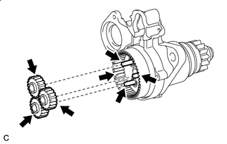

High-temperature Grease Apply high-temperature grease to the 3 planetary gears, 3 planetary gear shafts and starter drive housing assembly.
-
Install the 3 planetary gears to the starter drive housing assembly.
-
- Click here
INSTALL STARTER ARMATURE ASSEMBLY
-
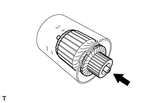
Install the starter armature assembly to the starter yoke assembly.
-
- Click here
INSTALL STARTER BRUSH HOLDER ASSEMBLY
-
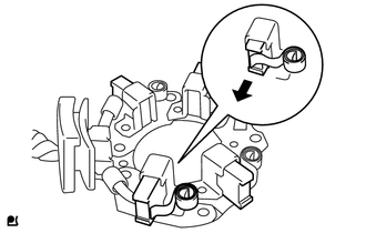
Hold the brush spring back and set the 4 brushes as shown in the illustration.
-
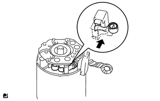
Install the starter brush holder assembly to the starter armature assembly and push in the 4 brushes as shown in the illustration.
-
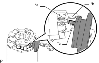
*a Grommet *b Negative (-) Brush Holder Plate *c Positive (+) Motor Lead Wire Fit the protrusion of the grommet between the negative (-) brush holder plate and positive (+) motor lead wire.
-
- Click here
INSTALL STARTER COMMUTATOR END FRAME ASSEMBLY
-
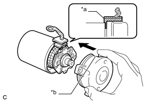
*a Lead Wire Rubber *b Cutout Install the starter commutator end frame assembly to the starter yoke assembly.
Note:Align the lead wire rubber of the starter yoke assembly with the cutout of the starter commutator end frame assembly.
-
Install the 2 screws.
1.5 N*m 15 kgf*cm 13 in.*lbf
-
- Click here
INSTALL STARTER ARMATURE PLATE
-
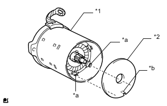
*1 Starter Yoke Assembly *2 Starter Armature Plate *a Stopper *b Protrusion Align the starter armature plate so that the protrusion fits between the stoppers of the starter yoke assembly, and install the starter armature plate.
Note:Make sure the protrusion of the starter armature plate is inserted between the stoppers of the starter yoke assembly.
-
- Click here
INSTALL STARTER YOKE ASSEMBLY
-
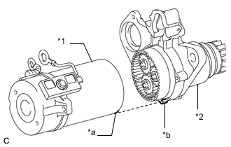
*1 Starter Yoke Assembly *2 Starter Drive Housing Assembly *a Cutout *b Protrusion Align the cutout of the starter yoke assembly with the protrusion of the starter drive housing assembly.
-
Using a T25 "TORX" socket wrench, install the 2 through bolts.
6.0 N*m 61 kgf*cm 53 in.*lbf
-
-
*a Pinion Drive Lever *b Plunger *c Return Spring *d Magnet Switch *e Plunger Cover *f Protrusion *g Ventilation Hole *h Hook *i 90°Click here
INSTALL REPAIR SERVICE STARTER KIT
-
Hang the hook of the plunger on the pinion drive lever and install the repair service starter kit.
Note:
-
Make sure the return spring is not resting on the protrusion of the plunger or pushed between the magnet switch and plunger.
-
Install the plunger cover so that the ventilation hole is positioned as shown in the illustration.
-
-
Install the 2 nuts.
7.5 N*m 76 kgf*cm 66 in.*lbf
-
- Click here
INSTALL STARTER INRUSH CURRENT REDUCTION RELAY
-
Install the starter inrush current reduction relay to the starter drive housing assembly with the 2 bolts.
7.9 N*m 81 kgf*cm 70 in.*lbf -
Connect the lead wire to terminal M with the nut.
9.0 N*m 92 kgf*cm 80 in.*lbf
-
- Click here
INSTALL HARNESS
-
Connect the 2 harness connectors to install the harness.
-
- Click here
INSTALL WIRE HARNESS
-
Connect the noise filter harness to the repair service starter kit.
-
Install the wire harness to the starter assembly with the 2 nuts.
9.0 N*m 92 kgf*cm 80 in.*lbf
-