ГОЛОВКА БЛОКА ЦИЛИНДРОВ РАЗБОРКА

CAUTION / NOTICE / HINT
The necessary procedures (adjustment, calibration, initialization, or registration) that must be performed after parts are removed, installed, or replaced during the engine assembly removal/installation are shown below.
| Replacement Part or Procedure | Necessary Procedures | Effects/Inoperative when not Performed | Link |
|---|---|---|---|
| Battery terminal is disconnected/reconnected | Drive the vehicle until stop and start control is permitted (approximately 15 to 40 minutes) | Stop and start system | |
| Memorize steering angle neutral point | Panoramic view monitor system | ||
| Initialize back door lock | Power door lock control system | ||
| Initialize servo motor | Air conditioning system | ||
| Reset slide door close position | Power slide door system | ||
| Reset back door close position | Power back door system | ||
| Replacement of ECM | Perform Vehicle Identification Number (VIN) or frame number registration |
|
|
| ECU Communication ID Registration (Immobiliser system) | Engine start function | See Service Bulletin for the registration method. | |
| Perform code registration (Immobiliser system) |
|
See Service Bulletin for the registration method. | |
| Perform the following procedures in the order shown:
|
|
||
| Replacement of continuously variable transaxle assembly | Perform the following procedures in the order shown:
|
|
|
|
Inspection After Repair |
|
|
| Replacement of starter assembly | Clear Number of Starter Operations | Stop and start system | |
|
Bleed the oil pump assembly with motor (continuously variable transaxle assembly) | ||
| Front wheel alignment adjustment |
|
|
|
| Work that changes the vehicle height such as replacement or removal/installation of the rear height control sensor sub-assembly LH or replacement of suspension components | Initialize headlight light control ECU sub-assembly LH | Headlight leveling function | |
| Removal/installtaion of the radiator grille | Television camera view adjustment | Panoramic view monitor system |
PROCEDURE
-
REMOVE INTAKE VALVE
Tech Tips
Type A and Type B can be distinguished by the shape of the compression spring.
Type Compression Spring Shape A Straight B Tapered 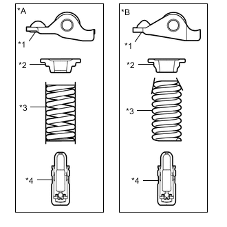
*A Type A *B Type B *1 No. 1 Valve Rocker Arm Sub-assembly *2 Valve Spring Retainer *3 Compression Spring *4 Valve Lash Adjuster Assembly
-
Type A:
-
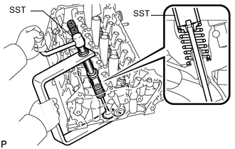
Using SST, compress the compression spring and remove the valve spring retainer lock.
- SST
- 09202-70020 ( 09202-00010, 09202-01010, 09202-01020 )
-
Remove the valve spring retainer, compression spring and intake valve from the cylinder head sub-assembly.
Tech Tips
Arrange the removed parts in such a way that they can be reinstalled to their original locations.
-
-
Type B:
-
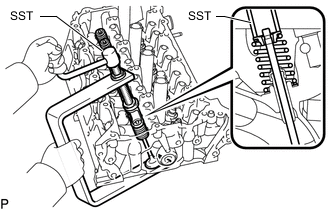
Using SST, compress the compression spring and remove the valve spring retainer lock.
- SST
- 09202-70020
- 09202-00021
-
Remove the valve spring retainer, compression spring and intake valve from the cylinder head sub-assembly.
Tech Tips
Arrange the removed parts in such a way that they can be reinstalled to their original locations.
-
-
-
REMOVE EXHAUST VALVE
Tech Tips
Type A and Type B can be distinguished by the shape of the compression spring.
Type Compression Spring Shape A Straight B Tapered
*A Type A *B Type B *1 No. 1 Valve Rocker Arm Sub-assembly *2 Valve Spring Retainer *3 Compression Spring *4 Valve Lash Adjuster Assembly
-
Type A:
-
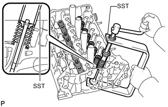
Using SST, compress the compression spring and remove the valve spring retainer lock.
- SST
- 09202-70020 ( 09202-00010, 09202-01010, 09202-01020 )
-
Remove the valve spring retainer, compression spring and exhaust valve from the cylinder head sub-assembly.
Tech Tips
Arrange the removed parts in such a way that they can be reinstalled to their original locations.
-
-
Type B:
-
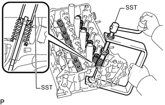
Using SST, compress the compression spring and remove the valve spring retainer lock.
- SST
- 09202-70020
- 09202-00021
-
Remove the valve spring retainer, compression spring and exhaust valve from the cylinder head sub-assembly.
Tech Tips
Arrange the removed parts in such a way that they can be reinstalled to their original locations.
-
-
-
REMOVE VALVE STEM OIL SEAL
-
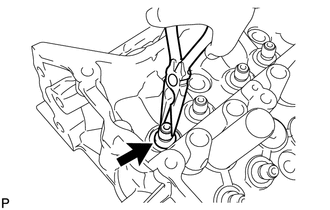
Using needle-nose pliers, remove the valve stem oil seal.
-
-
REMOVE VALVE SPRING SEAT
-
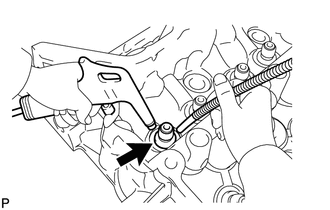
Using compressed air and a Magnet Hand, remove the valve spring seat by blowing air onto them.
-
-
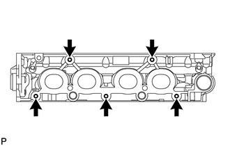
REMOVE NO. 1 STRAIGHT SCREW PLUG
Note
If coolant leaks from a No. 1 straight screw plug or a plug is corroded, replace it.
-
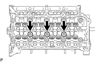
Using a 10 mm hexagon wrench, remove the 3 No. 1 straight screw plugs and 3 gaskets.
-
-
REMOVE NO. 2 STRAIGHT SCREW PLUG
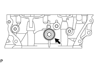
Note
If coolant leaks from the No. 2 straight screw plug or a plug is corroded, replace it.
-
Using a 14 mm hexagon wrench, remove the No. 2 straight screw plug and gasket.
-
-
REMOVE STUD BOLT
Note
If a stud bolt is deformed or its threads are damaged, replace it.
-
Using an E7 or E8 "TORX" socket wrench, remove the 5 stud bolts.
-