ПРОКЛАДКА ГОЛОВКИ БЛОКА ЦИЛИНДРОВ УСТАНОВКА

PROCEDURE
-
INSPECT VALVE LASH ADJUSTER ASSEMBLY
-
INSPECT NO. 1 VALVE ROCKER ARM SUB-ASSEMBLY
-
INSTALL CYLINDER HEAD GASKET
-
Clean the cylinder block sub-assembly and cylinder head sub-assembly with solvent.
-
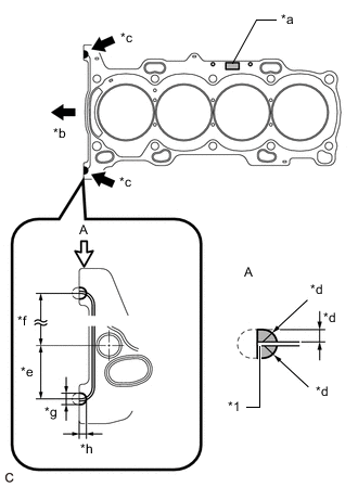
*1 Cylinder Head Gasket *a Lot No. *b Front of Engine *c Seal Packing *d 3.0 to 5.0 mm (0.118 to 0.197 in.) *e 38 mm (1.50 in.) *f 152.5 mm (6.00 in.) *g 7.0 to 9.0 mm (0.276 to 0.354 in.) *h 5.0 to 7.0 mm (0.197 to 0.276 in.) Apply a continuous line of seal packing to a new cylinder head gasket as shown in the illustration.
Seal Packing Toyota Genuine Seal Packing Black, Three Bond 1207B or equivalent Note
-
Remove any oil from the contact surfaces.
-
Install the cylinder head gasket within 3 minutes and tighten the cylinder head bolts within 15 minutes of applying seal packing.
-
-
Place the cylinder head gasket on the cylinder block sub-assembly with the Lot No. stamp facing upward.
Note
Pay attention to the installation direction.
-
-
INSTALL CYLINDER HEAD SUB-ASSEMBLY
Tech Tips
The cylinder head bolts are tightened in 4 progressive steps.
-
Place the cylinder head sub-assembly on the cylinder block sub-assembly.
Note
-
Ensure that no oil is on the contact surface of the cylinder head sub-assembly.
-
Place the cylinder head sub-assembly on the cylinder block sub-assembly gently in order not to damage the cylinder head gasket with the bottom of the cylinder head sub-assembly.
-
-
Install the 10 plate washers to the 10 cylinder head bolts.
-
Apply a light coat of engine oil to the threads and under the heads of the cylinder head bolts.
-
Step 1:
-
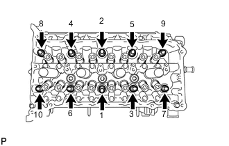
Using a 10 mm bi-hexagon wrench, install and uniformly tighten the 10 cylinder head bolts in several steps in the order shown in the illustration.
- Torque:
- 36 N*m { 367 kgf*cm, 27 ft.*lbf }
Note
Do not drop the plate washers for the cylinder head bolts into the cylinder head sub-assembly.
-
-
Step 2:
-
Check that the cylinder head bolts are tightened to the specified torque.
- Torque:
- 36 N*m { 367 kgf*cm, 27 ft.*lbf }
-
-
Step 3:
-
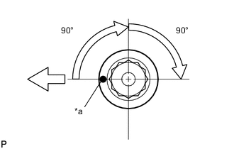
*a Paint Mark 
Front of Engine Mark each cylinder head bolt head with paint as shown in the illustration.
-
Tighten the cylinder head bolts 90° in the order shown in step 1.
-
-
Step 4:
-
Tighten the cylinder head bolts another 90° in the order shown in step 1.
-
Check that the paint marks are now facing rearward.
Note
-
Do not install the timing chain cover assembly for at least 2 hours after installation.
-
Do not start the engine for at least 2 hours after installation.
-
Thoroughly wipe off any seal packing that has seeped out onto the front side of the engine.
Tech Tips
Perform "Inspection After Repair" after replacing the cylinder head sub-assembly.
-
-
-
-
INSTALL VALVE STEM CAP
-
INSTALL VALVE LASH ADJUSTER ASSEMBLY
-
INSTALL NO. 1 VALVE ROCKER ARM SUB-ASSEMBLY
-
INSTALL NO. 2 CAMSHAFT BEARING
-
INSTALL NO. 1 CAMSHAFT BEARING
-
INSTALL CAMSHAFT
-
INSTALL NO. 2 CAMSHAFT
-
INSTALL OIL CONTROL VALVE FILTER
-
INSTALL CAMSHAFT BEARING CAP
-
INSTALL CAMSHAFT HOUSING SUB-ASSEMBLY
-
INSTALL CAMSHAFT TIMING GEAR ASSEMBLY
-
INSTALL CAMSHAFT TIMING EXHAUST GEAR ASSEMBLY
-
ADD ENGINE OIL
-
SET NO. 1 CYLINDER TO TDC/COMPRESSION
-
Temporarily install the crankshaft pulley bolt.
-
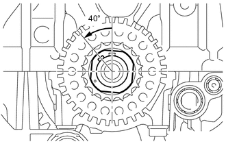
Rotate the crankshaft 40° counterclockwise to position the crankshaft pulley key as shown in the illustration.
-
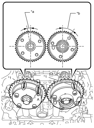
*1 Timing Mark *a Approximately 7° *b Approximately 32° Check that the timing marks of the camshaft timing gear assembly and camshaft timing exhaust gear assembly are as shown in the illustration.
Tech Tips
"A" is not a timing mark.
-
-
INSTALL NO. 1 CHAIN VIBRATION DAMPER
-
INSTALL CHAIN SUB-ASSEMBLY
-
INSTALL CHAIN TENSIONER SLIPPER
-
INSTALL NO. 1 CHAIN TENSIONER ASSEMBLY
-
INSTALL TIMING CHAIN GUIDE
-
CHECK NO. 1 CYLINDER TO TDC/COMPRESSION
-
Temporarily install the crankshaft pulley bolt.
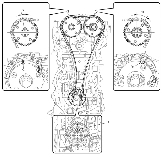
*1 Crankshaft Pulley Key - - *a Approximately 7° *b Approximately 32° *c Timing Mark - - -
Rotate the crankshaft clockwise and align the crankshaft pulley key as shown in the illustration.
-
Check that the timing marks on the camshaft timing sprocket and camshaft timing gear assembly are as shown in the illustration.
Tech Tips
"A" is not a timing mark.
-
Remove the crankshaft pulley bolt.
-
-
CONNECT NO. 2 VENTILATION HOSE
-
INSTALL FUEL DELIVERY PIPE
-
INSTALL INTAKE MANIFOLD
-
INSTALL THROTTLE BODY WITH MOTOR ASSEMBLY
-
INSTALL EXHAUST MANIFOLD CONVERTER SUB-ASSEMBLY (TWC: Front Catalyst)
-
INSTALL NO. 1 EXHAUST MANIFOLD HEAT INSULATOR
-
INSTALL NO. 2 MANIFOLD STAY
-
INSTALL MANIFOLD STAY
-
INSTALL TIMING CHAIN COVER SUB-ASSEMBLY