| DTC Code | DTC Name |
|---|---|
| Both Manual and Automatic Operation of Active Rear Wing does not Operate |
DESCRIPTION
When the active rear wing cannot be operated by either manual or automatic operation, there may be a malfunction in the spoiler control ECU assembly power supply, ground circuit, spoiler control ECU assembly or No. 2 rear spoiler motor assembly may be malfunctioning.
CAUTION / NOTICE / HINT
Inspect the fuses for circuits related to this system before performing the following procedure.
PROCEDURE
- Click here
READ VALUE USING GTS
-
Connect the GTS to the DLC3.
-
Turn the engine switch on (IG).
-
Turn the GTS on.
-
Enter the following menus: Customize Setting / Others.
-
Check that the active rear wing system customize setting "Active Rear Wing Control" is set to "Permission".
- Others
Tester Display Description Default Setting ECU Active Rear Wing Control Active rear wing system permission/prohibition setting Prohibition 01:Permission,10:Prohibition Spoiler control ECU assembly -
-
-
OK The active rear wing system customize setting "Active Rear Wing Control" is set to "Permission". Result Proceed to OK NG - Others
- OKClick here
- NG
PERFORM CUSTOMIZE FUNCTION (Change setting to "Permission")Click here
-
- Click here
CHECK FOR DTC
-
Check for DTCs.
- Body Electrical > Active Rear Wing > Trouble Codes
-
-
OK DTCs are not output. Result Proceed to OK NG
- OKClick here
- NG
GO TO DIAGNOSTIC TROUBLE CODE CHARTClick here
-
- Click here
READ VALUE USING GTS
-
Connect the GTS to the DLC3.
-
Turn the engine switch on (IG).
-
Turn the GTS on.
-
Enter the following menus: Body Electrical / Active Rear Wing / Data List.
-
Read the Data List according to the display on the GTS.
- Body Electrical > Active Rear Wing > Data List
Tester Display Measurement Item Range Normal Condition Diagnostic Note Vehicle Speed Information Vehicle speed signal reception condition OK or NG OK: Vehicle speed signal is valid
NG: Vehicle speed signal is invalid
- -
-
- Body Electrical > Active Rear Wing > Data List
Tester Display Vehicle Speed Information -
-
-
-
Result Result Proceed to OK is displayed on the GTS A NG is displayed on the GTS B - Body Electrical > Active Rear Wing > Data List
- AClick here
- B
GO TO VEHICLE STABILITY CONTROL SYSTEMClick here
-
- Click here
CHECK HARNESS AND CONNECTOR (BODY GROUND)
-
Disconnect the U38 spoiler control ECU assembly connector.
-
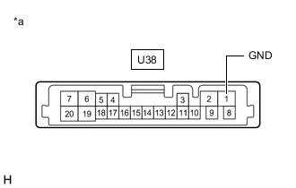
*a Front view of wire harness connector
(to Spoiler Control ECU Assembly)
Measure the resistance according to the value(s) in the table below.
Standard Resistance Tester Connection Condition Specified Condition U38-1 (GND) - Body ground Engine switch on (IG) 11 to 14 V Result Proceed to OK NG
- OKClick here
- NG
REPAIR OR REPLACE HARNESS OR CONNECTOR
-
- Click here
CHECK HARNESS AND CONNECTOR (POWER SUPPLY)
-
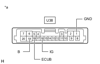
*a Front view of wire harness connector
(to Spoiler Control ECU Assembly)
Measure the voltage according to the value(s) in the table below.
Standard Voltage Tester Connection Condition Specified Condition U38-18 (ECUB) - U38-1 (GND) Always 11 to 14 V U38-19 (B) - U38-1 (GND) Always 11 to 14 V U38-16 (IG) - U38-1 (GND) Engine switch off Below 1 V U38-16 (IG) - U38-1 (GND) Engine switch on (IG) 11 to 14 V Result Proceed to OK NG
- OKClick here
- NG
REPAIR OR REPLACE HARNESS OR CONNECTOR
-
- Click here
INSPECT NO. 2 REAR SPOILER MOTOR ASSEMBLY
-
Remove the No. 2 rear spoiler motor assembly.
-
Inspect the No. 2 rear spoiler motor assembly.
Result Proceed to OK NG
- OKClick here
- NG
REPLACE NO. 2 REAR SPOILER MOTOR ASSEMBLYClick here
-
- Click here
CHECK HARNESS AND CONNECTOR (SPOILER CONTROL ECU ASSEMBLY - NO. 2 REAR SPOILER MOTOR ASSEMBLY)
-
Measure the resistance according to the value(s) in the table below.
Standard Resistance Tester Connection Condition Specified Condition U38-6 (RSM+) - F1-3 (U) Always Below 1 Ω U38-6 (RSM+) or F1-3 (U) - Body ground Always 10 kΩ or higher U38-7 (RSM-) - F1-1 (D) Always Below 1 Ω U38-7 (RSM-) or F1-1 (D) - Body ground Always 10 kΩ or higher Result Proceed to OK NG
- OK
REPLACE SPOILER CONTROL ECU ASSEMBLYClick here
- NG
REPAIR OR REPLACE HARNESS OR CONNECTOR
-