ACTIVE REAR WING SYSTEM, Diagnostic DTC:B1311
| DTC Code | DTC Name |
|---|---|
| B1311 | Hall IC Pulse Sensor Main or Sub |
DESCRIPTION
This DTC is stored when a malfunction of either Hall IC (Hall IC1 or Hall IC2) is detected.
| DTC No. | Detection Item | DTC Detection Condition | Trouble Area |
|---|---|---|---|
| B1311 | Hall IC Pulse Sensor Main or Sub | When the No. 2 rear spoiler motor assembly is operating, a pulse signal of 20 edges or more is received from either Hall IC (Hall IC1 or Hall IC2) but a pulse signal is not received from the other Hall IC. |
|
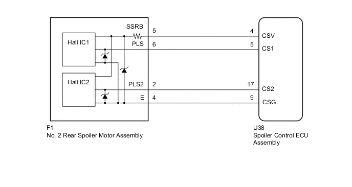
WIRING DIAGRAM
CAUTION / NOTICE / HINT
CAUTION:
Be careful not to get pinched by the active rear wing assembly when the active rear wing is operating.
PROCEDURE
-
CHECK CONNECTOR CONNECTION
-
Check that the connectors are properly connected to the spoiler control ECU assembly and No. 2 rear spoiler motor assembly.
OK Connectors are properly connected. Result Proceed to OK NG
NG 
CONNECT CONNECTORS PROPERLY
OK 
-
-
CLEAR DTC
-
Clear the DTCs.
Body Electrical > Active Rear Wing > Clear DTCsResult Proceed to NEXT
NEXT
-
-
CHECK FOR DTC
-
Raise and retract the active rear wing by manual operation.
-
Check for DTCs.
Body Electrical > Active Rear Wing > Trouble CodesOK DTC B1311 is not output. Result Proceed to OK NG
OK
USE SIMULATION METHOD TO CHECK Click here
NG
-
-
CHECK NO. 2 REAR SPOILER MOTOR ASSEMBLY
-
Connect the GTS to the DLC3.
-
Turn the engine switch on (IG).
-
Turn the GTS on.
-
Enter the following menus: Body Electrical / Active Rear Wing / Active Test.
-
Perform the Active Test to raise or retract the active rear wing.
Note
-
Before performing the Active Test, check that "Init" is displayed for the Data List item "Initialization Status". If "Init" is not displayed, initialize the active rear wing system.
-
While performing the Active Test, if the active rear wing is stopped during an operation, it is necessary to perform initialization.
Body Electrical > Active Rear Wing > Active TestTester Display Measurement Item Control Range Diagnostic Note Wing Extend Active rear wing rise operation OFF/ON - Wing Fold Active rear wing retract operation OFF/ON -
Body Electrical > Active Rear Wing > Active TestTester Display Wing Extend
Body Electrical > Active Rear Wing > Active TestTester Display Wing Fold -
-
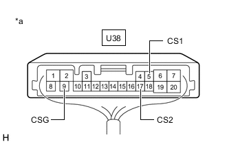
*a Component with harness connected
(Spoiler Control ECU Assembly)
Measure the voltage according to the value(s) in the table below.
Standard Voltage Tester Connection Condition Specified Condition U38-5 (CS1) - U38-9 (CSG) Active rear wing rise or retract operation being performed Pulse generation
(Below 1 V ←→ 9.5 to 13.33 V)
U38-17 (CS2) - U38-9 (CSG) Active rear wing rise or retract operation being performed Pulse generation
(Below 1 V ←→ 9.5 to 13.33 V)
Result Proceed to OK NG
OK
REPLACE SPOILER CONTROL ECU ASSEMBLY Click here
NG
-
-
CHECK HARNESS AND CONNECTOR (SPOILER CONTROL ECU ASSEMBLY - NO. 2 REAR SPOILER MOTOR ASSEMBLY)
-
Disconnect the U38 spoiler control ECU assembly connector.
-
Disconnect the F1 No. 2 rear spoiler motor assembly connector.
-
Measure the resistance according to the value(s) in the table below.
Standard Resistance Tester Connection Condition Specified Condition U38-5 (CS1) - F1-6 (PLS) Always Below 1 Ω U38-5 (CS1) or F1-6 (PLS) - Body ground Always 10 kΩ or higher U38-17 (CS2) - F1-2 (PLS2) Always Below 1 Ω U38-17 (CS2) or F1-2 (PLS2) - Body ground Always 10 kΩ or higher Result Proceed to OK NG
OK
REPLACE NO. 2 REAR SPOILER MOTOR ASSEMBLY Click here
NG
REPAIR OR REPLACE HARNESS OR CONNECTOR
-