| DTC Code | DTC Name |
|---|---|
| Headlight Dimmer Switch Circuit |
DESCRIPTION
The main body ECU (multiplex network body ECU) receives the following switch information:
-
Light control switch in off*1, tail, head or AUTO position
-
Dimmer switch in high, low or high flash (pass) position
-
Fog light switch in rear*2 or off position
-
*1: w/ Light Control Switch Off Position
-
*2: w/ Rear Fog Light
WIRING DIAGRAM
Click here
-
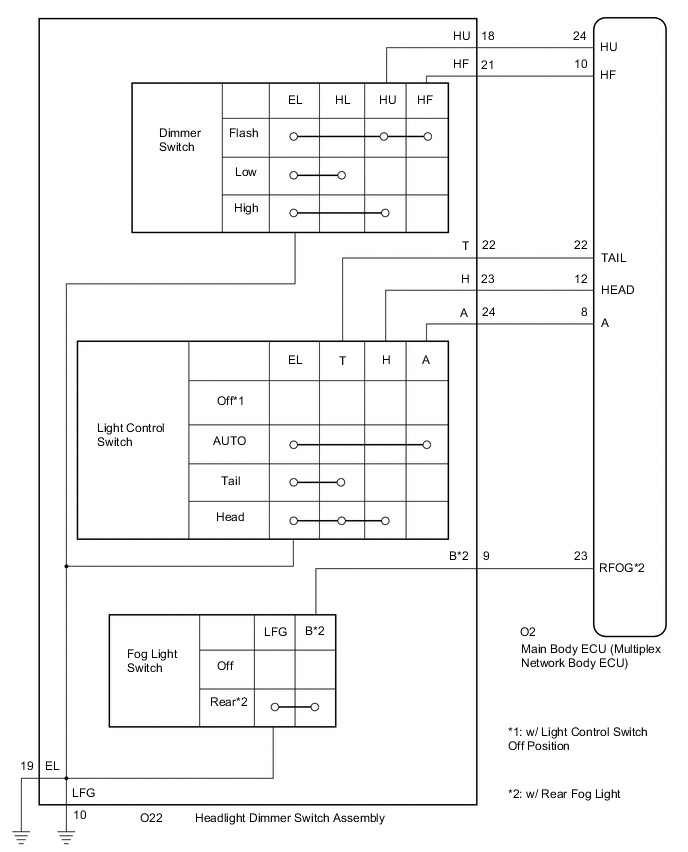
for Light Control Switch LH Side Type
-
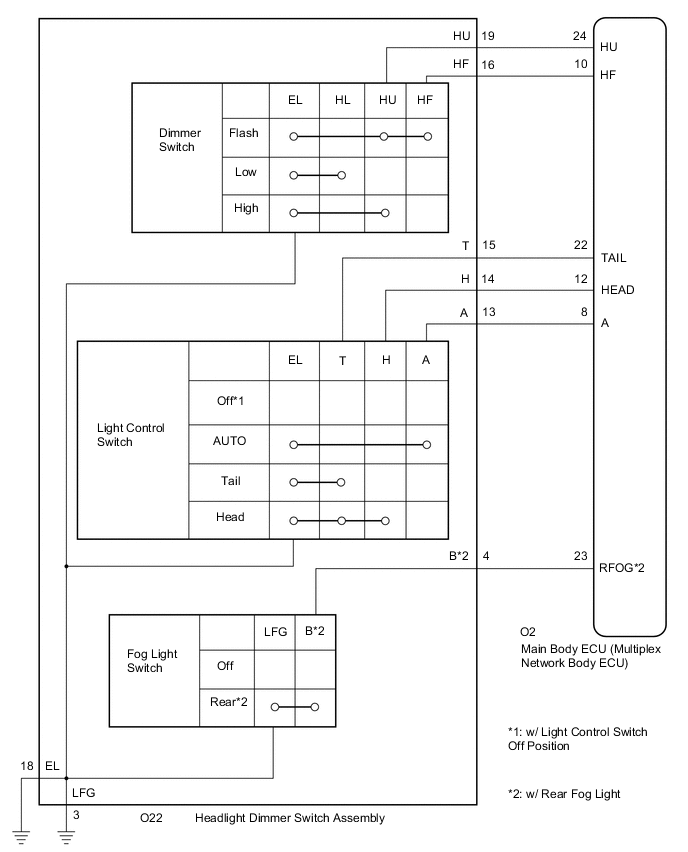
for Light Control Switch RH Side Type
CAUTION / NOTICE / HINT
Before replacing the main body ECU (multiplex network body ECU), refer to Service Bulletin.
PROCEDURE
- Click here
READ VALUE USING GTS
-
Connect the GTS to the DLC3.
-
Turn the engine switch on (IG).
-
Turn the GTS on.
-
Enter the following menus: Body Electrical / Main Body / Data List.
-
Read the Data List according to the display on the GTS.
- Body Electrical > Main Body > Data List
Tester Display Measurement Item Range Normal Condition Diagnostic Note Dimmer SW Dimmer switch high position signal ON or OFF ON: Dimmer switch in high or high flash position
OFF: Dimmer switch in low position
- Passing Light SW Dimmer switch high flash position (pass) signal ON or OFF ON: Dimmer switch in high flash position
OFF: Dimmer switch not in high flash position
- Rear Fog Light SW Fog light switch rear position signal ON or OFF ON: Fog light switch in rear position
OFF: Fog light switch off
* Auto Light SW Light control switch AUTO position signal ON or OFF ON: Light control switch in AUTO position
OFF: Light control switch not in AUTO position
- Head Light SW (Head) Light control switch head position signal ON or OFF ON: Light control switch in head position
OFF: Light control switch not in head position
- Head Light SW (Tail) Light control switch tail position signal ON or OFF ON: Light control switch in tail or head position
OFF: Light control switch not in tail or head position
- -
-
-
*: w/ Rear Fog Light
- Body Electrical > Main Body > Data List
Tester Display Dimmer SW Passing Light SW Rear Fog Light SW Auto Light SW Head Light SW (Head) Head Light SW (Tail) -
-
-
-
OK Normal conditions listed above are displayed. Result Proceed to OK NG - Body Electrical > Main Body > Data List
- OK
PROCEED TO NEXT SUSPECTED AREA SHOWN IN PROBLEM SYMPTOMS TABLEClick here
- NGClick here
-
- Click here
INSPECT HEADLIGHT DIMMER SWITCH ASSEMBLY
Tip:Inspect the items that did not change when reading the Data List.
-
Remove the headlight dimmer switch assembly.
-
Measure the resistance according to the value(s) in the table below.
-
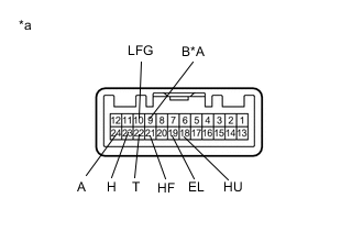
*A w/ Rear Fog Light *a Component without harness connected
(Headlight Dimmer Switch Assembly)
for Light Control Switch LH Side Type:
Standard Resistance Table 1. Light Control Switch Tester Connection Condition Specified Condition 22 (T) - 19 (EL) Light control switch off*1 10 kΩ or higher 23 (H) - 19 (EL) Light control switch off*1 10 kΩ or higher 24 (A) - 19 (EL) Light control switch off*1 10 kΩ or higher 22 (T) - 19 (EL) Light control switch in tail position Below 1 Ω 22 (T) - 19 (EL) Light control switch in head position Below 1 Ω 23 (H) - 19 (EL) Light control switch in head position Below 1 Ω 24 (A) - 19 (EL) Light control switch in AUTO position Below 1 Ω Table 2. Dimmer Switch Tester Connection Condition Specified Condition 18 (HU) - 19 (EL) Dimmer switch in high position Below 1 Ω 18 (HU) - 19 (EL) Dimmer switch in high flash position Below 1 Ω 21 (HF) - 19 (EL) Dimmer switch in high flash position Below 1 Ω Table 3. Fog Light Switch Tester Connection Condition Specified Condition 9 (B) - 10 (LFG)*2 Fog light switch off 10 kΩ or higher 9 (B) - 10 (LFG)*2 Fog light switch in rear position Below 1 Ω
-
*1: w/ Light Control Switch Off Position
-
*2: w/ Rear Fog Light
-
-
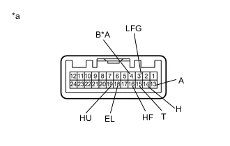
*A w/ Rear Fog Light *a Component without harness connected
(Headlight Dimmer Switch Assembly)
for Light Control Switch RH Side Type:
Standard Resistance Table 4. Light Control Switch Tester Connection Condition Specified Condition 15 (T) - 18 (EL) Light control switch off*1 10 kΩ or higher 14 (H) - 18 (EL) Light control switch off*1 10 kΩ or higher 13 (A) - 18 (EL) Light control switch off*1 10 kΩ or higher 15 (T) - 18 (EL) Light control switch in tail position Below 1 Ω 15 (T) - 18 (EL) Light control switch in head position Below 1 Ω 14 (H) - 18 (EL) Light control switch in head position Below 1 Ω 13 (A) - 18 (EL) Light control switch in AUTO position Below 1 Ω Table 5. Dimmer Switch Tester Connection Condition Specified Condition 19 (HU) - 18 (EL) Dimmer switch in high position Below 1 Ω 19 (HU) - 18 (EL) Dimmer switch in high flash position Below 1 Ω 16 (HF) - 18 (EL) Dimmer switch in high flash position Below 1 Ω Table 6. Fog Light Switch Tester Connection Condition Specified Condition 4 (B) - 3 (LFG)*2 Fog light switch off 10 kΩ or higher 4 (B) - 3 (LFG)*2 Fog light switch in rear position Below 1 Ω
-
*1: w/ Light Control Switch Off Position
-
*2: w/ Rear Fog Light
-
Result Proceed to OK NG -
- OKClick here
- NG
REPLACE HEADLIGHT DIMMER SWITCH ASSEMBLYClick here
-
- Click here
CHECK HARNESS AND CONNECTOR (HEADLIGHT DIMMER SWITCH ASSEMBLY - MAIN BODY ECU (MULTIPLEX NETWORK BODY ECU))
-
Disconnect the O2 main body ECU (multiplex network body ECU) connector.
-
Measure the resistance according to the value(s) in the table below.
-
for Light Control Switch LH Side Type:
Standard Resistance Tester Connection Condition Specified Condition O22-9 (B) - O2-23 (RFOG)* Always Below 1 Ω O22-18 (HU) - O2-24 (HU) Always Below 1 Ω O22-21 (HF) - O2-10 (HF) Always Below 1 Ω O22-22 (T) - O2-22 (TAIL) Always Below 1 Ω O22-23 (H) - O2-12 (HEAD) Always Below 1 Ω O22-24 (A) - O2-8 (A) Always Below 1 Ω O22-9 (B) - Body ground* Always 10 kΩ or higher O22-18 (HU) - Body ground Always 10 kΩ or higher O22-21 (HF) - Body ground Always 10 kΩ or higher O22-22 (T) - Body ground Always 10 kΩ or higher O22-23 (H) - Body ground Always 10 kΩ or higher O22-24 (A) - Body ground Always 10 kΩ or higher O22-19 (EL) - Body ground Always Below 1 Ω O22-10 (LFG) - Body ground Always Below 1 Ω
-
*: w/ Rear Fog Light
-
-
for Light Control Switch RH Side Type:
Standard Resistance Tester Connection Condition Specified Condition O22-4 (B) - O2-23 (RFOG)* Always Below 1 Ω O22-19 (HU) - O2-24 (HU) Always Below 1 Ω O22-16 (HF) - O2-10 (HF) Always Below 1 Ω O22-15 (T) - O2-22 (TAIL) Always Below 1 Ω O22-14 (H) - O2-12 (HEAD) Always Below 1 Ω O22-13 (A) - O2-8 (A) Always Below 1 Ω O22-4 (B) - Body ground* Always 10 kΩ or higher O22-19 (HU) - Body ground Always 10 kΩ or higher O22-16 (HF) - Body ground Always 10 kΩ or higher O22-15 (T) - Body ground Always 10 kΩ or higher O22-14 (H) - Body ground Always 10 kΩ or higher O22-13 (A) - Body ground Always 10 kΩ or higher O22-18 (EL) - Body ground Always Below 1 Ω O22-3 (LFG) - Body ground Always Below 1 Ω
-
*: w/ Rear Fog Light
-
Result Proceed to OK NG -
- OK
REPLACE MAIN BODY ECU (MULTIPLEX NETWORK BODY ECU)Click here
- NG
REPAIR OR REPLACE HARNESS OR CONNECTOR
-