Click here
-
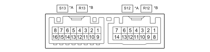
*A for LHD *B for RHD CHECK OUTER MIRROR CONTROL ECU ASSEMBLY (DRIVER DOOR)
-
Disconnect the S12*1 or R12*2 outer mirror control ECU assembly (driver door) connector.
-
*1: for LHD
-
*2: for RHD
-
-
Measure the voltage and resistance according to the value(s) in the table below.
Tip:Measure the values on the wire harness side with the connector disconnected.
Table 1. for LHD Terminal No. (Symbol) Wiring Color Terminal Description Condition Specified Condition S12-14 (BDR) - Body ground G - Body ground +B power supply Always 11 to 14 V S12-6 (CPUB) - Body ground L - Body ground +B power supply Always 11 to 14 V S12-5 (SIG) - Body ground B - Body ground Ignition power supply Engine switch off → on (IG) Below 1 V → 11 to 14 V S12-7 (GND) - Body ground W-B - Body ground Ground Always Below 1 Ω Table 2. for RHD Terminal No. (Symbol) Wiring Color Terminal Description Condition Specified Condition R12-14 (BDR) - Body ground B - Body ground +B power supply Always 11 to 14 V R12-6 (CPUB) - Body ground LG - Body ground +B power supply Always 11 to 14 V R12-5 (SIG) - Body ground R - Body ground Ignition power supply Engine switch off → on (IG) Below 1 V → 11 to 14 V R12-7 (GND) - Body ground W-B - Body ground Ground Always Below 1 Ω -
Reconnect the S12*1 or R12*2 outer mirror control ECU assembly (driver door) connector.
-
*1: for LHD
-
*2: for RHD
-
-
Measure the voltage according to the value(s) in the table below.
Table 3. for LHD Terminal No. (Symbol) Wiring Color Terminal Description Condition Specified Condition S13-3 (MR+) - Body ground P - Body ground Power retract mirror motor drive voltage Outer rear view mirror assembly (driver door) being retracted 11 to 14 V Outer rear view mirror assembly (driver door) stopped Below 1 V S13-11 (MR-) - Body ground R - Body ground Power retract mirror motor drive voltage Outer rear view mirror assembly (driver door) returning 11 to 14 V Outer rear view mirror assembly (driver door) stopped Below 1 V S13-1 (LMVR) - S13-10 (LM+R) V - B Vertical mirror motor drive voltage Driver door mirror surface moving upward → stopped 11 to 14 V → Below 1 V S13-10 (LM+R) - S13-1 (LMVR) B - V Vertical mirror motor drive voltage Driver door mirror surface moving downward → stopped 11 to 14 V → Below 1 V S13-10 (LM+R) - S13-9 (LMHR) B - GR Horizontal mirror motor drive voltage Driver door mirror surface moving right → stopped 11 to 14 V → Below 1 V S13-9 (LMHR) - S13-10 (LM+R) GR - B Horizontal mirror motor drive voltage Driver door mirror surface moving left → stopped 11 to 14 V → Below 1 V S13-4 (HTR+) - S13-12 (HTR-) G - W-B Mirror heater relay drive voltage Mirror heater switch (rear window defogger switch) on 11 to 14 V S13-5 (LVC) - S12-7 (GND) Y - W-B Mirror position sensor power supply Engine switch on (IG) 4.75 to 5.25 V S13-6 (VSSR) - S12-7 (GND) SB - W-B Mirror position sensor signal Engine switch on (IG) 0 to 5 V S13-13 (HSSR) - S12-7 (GND) L - W-B Mirror position sensor signal Engine switch on (IG) 0 to 5 V S13-7 (EC+) - S13-15 (EC-) LG - W Automatic glare-resistant EC mirror drive signal Automatic glare-resistant EC mirror on 1.05 to 1.35 V Automatic glare-resistant EC mirror off Below 1 V S12-4 (M3) - S12-7 (GND) R - W-B M3 switch signal for seat memory switch M3 switch on Below 1 V M3 switch off 11 to 14 V S12-3 (M2) - S12-7 (GND) LG - W-B M2 switch signal for seat memory switch M2 switch on Below 1 V M2 switch off 11 to 14 V S12-2 (M1) - S12-7 (GND) BE - W-B M1 switch signal for seat memory switch M1 switch on Below 1 V M1 switch off 11 to 14 V S12-1 (MM) - S12-7 (GND) L - W-B SET switch signal for seat memory switch SET switch on Below 1 V SET switch off 11 to 14 V Table 4. for RHD Terminal No. (Symbol) Wiring Color Terminal Description Condition Specified Condition R13-3 (MR+) - Body ground P - Body ground Power retract mirror motor drive voltage Outer rear view mirror assembly (driver door) being retracted 11 to 14 V Outer rear view mirror assembly (driver door) stopped Below 1 V R13-11 (MR-) - Body ground R - Body ground Power retract mirror motor drive voltage Outer rear view mirror assembly (driver door) returning 11 to 14 V Outer rear view mirror assembly (driver door) stopped Below 1 V R13-1 (RMVR) - R13-10 (RM+R) V - B Vertical mirror motor drive voltage Driver door mirror surface moving upward → stopped 11 to 14 V → Below 1 V R13-10 (RM+R) - R13-1 (RMVR) B - V Vertical mirror motor drive voltage Driver door mirror surface moving downward → stopped 11 to 14 V → Below 1 V R13-10 (RM+R) - R13-9 (RMHR) B - GR Horizontal mirror motor drive voltage Driver door mirror surface moving right → stopped 11 to 14 V → Below 1 V R13-9 (RMHR) - R13-10 (RM+R) GR - B Horizontal mirror motor drive voltage Driver door mirror surface moving left → stopped 11 to 14 V → Below 1 V R13-4 (HTR+) - R13-12 (HTR-) G - W-B Mirror heater relay drive voltage Mirror heater switch (rear window defogger switch) on 11 to 14 V R13-5 (RVC) - R12-7 (GND) Y - W-B Mirror position sensor power supply Engine switch on (IG) 4.75 to 5.25 V R13-6 (VSSR) - R12-7 (GND) SB - W-B Mirror position sensor signal Engine switch on (IG) 0 to 5 V R13-13 (HSSR) - R12-7 (GND) L - W-B Mirror position sensor signal Engine switch on (IG) 0 to 5 V R13-7 (EC+) - R13-15 (EC-) LG - W Automatic glare-resistant EC mirror drive signal Automatic glare-resistant EC mirror on 1.05 to 1.35 V Automatic glare-resistant EC mirror off Below 1 V R12-4 (M3) - R12-7 (GND) R - W-B M3 switch signal for seat memory switch M3 switch on Below 1 V M3 switch off 11 to 14 V R12-3 (M2) - R12-7 (GND) LG - W-B M2 switch signal for seat memory switch M2 switch on Below 1 V M2 switch off 11 to 14 V R12-2 (M1) - R12-7 (GND) BE - W-B M1 switch signal for seat memory switch M1 switch on Below 1 V M1 switch off 11 to 14 V R12-1 (MM) - R12-7 (GND) L - W-B SET switch signal for seat memory switch SET switch on Below 1 V SET switch off 11 to 14 V
-
-
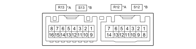
*A for LHD *B for RHD CHECK OUTER MIRROR CONTROL ECU ASSEMBLY (FRONT PASSENGER DOOR)
-
Disconnect the R12*1 or S12*2 outer mirror control ECU assembly (front passenger door) connector.
-
*1: for LHD
-
*2: for RHD
-
-
Measure the voltage and resistance according to the value(s) in the table below.
Tip:Measure the values on the wire harness side with the connector disconnected.
Table 5. for LHD Terminal No. (Symbol) Wiring Color Terminal Description Condition Specified Condition R12-14 (BDR) - Body ground B - Body ground +B power supply Always 11 to 14 V R12-6 (CPUB) - Body ground LG - Body ground +B power supply Always 11 to 14 V R12-5 (SIG) - Body ground R - Body ground Ignition power supply Engine switch off → on (IG) Below 1 V → 11 to 14 V R12-7 (GND) - Body ground W-B - Body ground Ground Always Below 1 Ω Table 6. for RHD Terminal No. (Symbol) Wiring Color Terminal Description Condition Specified Condition S12-14 (BDR) - Body ground G - Body ground +B power supply Always 11 to 14 V S12-6 (CPUB) - Body ground L - Body ground +B power supply Always 11 to 14 V S12-5 (SIG) - Body ground B - Body ground Ignition power supply Engine switch off → on (IG) Below 1 V → 11 to 14 V S12-7 (GND) - Body ground W-B - Body ground Ground Always Below 1 Ω -
Reconnect the R12*1 or S12*2 outer mirror control ECU assembly (front passenger door) connector.
-
*1: for LHD
-
*2: for RHD
-
-
Measure the voltage according to the value(s) in the table below.
Table 7. for LHD Terminal No. (Symbol) Wiring Color Terminal Description Condition Specified Condition R13-3 (MR+) - Body ground P - Body ground Power retract mirror motor drive voltage Outer rear view mirror assembly (front passenger door) being retracted 11 to 14 V Outer rear view mirror assembly (front passenger door) stopped Below 1 V R13-11 (MR-) - Body ground R - Body ground Power retract mirror motor drive voltage Outer rear view mirror assembly (front passenger door) returning 11 to 14 V Outer rear view mirror assembly (front passenger door) stopped Below 1 V R13-1 (RMVR) - R13-10 (RM+R) V - B Vertical mirror motor drive voltage Front passenger door mirror surface moving upward → stopped 11 to 14 V → Below 1 V R13-10 (RM+R) - R13-1 (RMVR) B - V Vertical mirror motor drive voltage Front passenger door mirror surface moving downward → stopped 11 to 14 V → Below 1 V R13-10 (RM+R) - R13-9 (RMHR) B - GR Horizontal mirror motor drive voltage Front passenger door mirror surface moving right → stopped 11 to 14 V → Below 1 V R13-9 (RMHR) - R13-10 (RM+R) GR - B Horizontal mirror motor drive voltage Front passenger door mirror surface moving left → stopped 11 to 14 V → Below 1 V R13-4 (HTR+) - R13-12 (HTR-) G - W-B Mirror heater relay drive voltage Mirror heater switch (rear window defogger switch) on 11 to 14 V R13-5 (RVC) - R12-7 (GND) Y - W-B Mirror position sensor power supply Engine switch on (IG) 4.75 to 5.25 V R13-6 (VSSR) - R12-7 (GND) SB - W-B Mirror position sensor signal Engine switch on (IG) 0 to 5 V R13-13 (HSSR) - R12-7 (GND) L - W-B Mirror position sensor signal Engine switch on (IG) 0 to 5 V R13-7 (EC+) - R13-15 (EC-) LG - W Automatic glare-resistant EC mirror drive signal Automatic glare-resistant EC mirror on 1.05 to 1.35 V Automatic glare-resistant EC mirror off Below 1 V Table 8. for RHD Terminal No. (Symbol) Wiring Color Terminal Description Condition Specified Condition S13-3 (MR+) - Body ground P - Body ground Power retract mirror motor drive voltage Outer rear view mirror assembly (front passenger door) being retracted 11 to 14 V Outer rear view mirror assembly (front passenger door) stopped Below 1 V S13-11 (MR-) - Body ground R - Body ground Power retract mirror motor drive voltage Outer rear view mirror assembly (front passenger door) returning 11 to 14 V Outer rear view mirror assembly (front passenger door) stopped Below 1 V S13-1 (LMVR) - S13-10 (LM+R) V - B Vertical mirror motor drive voltage Front passenger door mirror surface moving upward → stopped 11 to 14 V → Below 1 V S13-10 (LM+R) - S13-1 (LMVR) B - V Vertical mirror motor drive voltage Front passenger door mirror surface moving downward → stopped 11 to 14 V → Below 1 V S13-10 (LM+R) - S13-9 (LMHR) B - GR Horizontal mirror motor drive voltage Front passenger door mirror surface moving right → stopped 11 to 14 V → Below 1 V S13-9 (LMHR) - S13-10 (LM+R) GR - B Horizontal mirror motor drive voltage Front passenger door mirror surface moving left → stopped 11 to 14 V → Below 1 V S13-4 (HTR+) - S13-12 (HTR-) G - W-B Mirror heater relay drive voltage Mirror heater switch (rear window defogger switch) on 11 to 14 V S13-5 (LVC) - S12-7 (GND) Y - W-B Mirror position sensor power supply Engine switch on (IG) 4.75 to 5.25 V S13-6 (VSSR) - S12-7 (GND) SB - W-B Mirror position sensor signal Engine switch on (IG) 0 to 5 V S13-13 (HSSR) - S12-7 (GND) L - W-B Mirror position sensor signal Engine switch on (IG) 0 to 5 V S13-7 (EC+) - S13-15 (EC-) LG - W Automatic glare-resistant EC mirror drive signal Automatic glare-resistant EC mirror on 1.05 to 1.35 V Automatic glare-resistant EC mirror off Below 1 V
-