CAUTION / NOTICE / HINT
-
Use the same procedure for both the RH side and LH side.
-
The following procedure is for the LH side.
PROCEDURE
- Click here
PRECAUTION
Note:After turning the engine switch off, waiting time may be required before disconnecting the cable from the negative (-) battery terminal. Therefore, make sure to read the disconnecting the cable from the negative (-) battery terminal notices before proceeding with work.
- Click here
INSTALL FRONT DOOR BELT MOULDING
- Click here
INSTALL FRONT DOOR FRONT LOWER FRAME UPPER COVER
- Click here
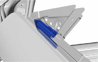
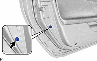
INSTALL FRONT DOOR PANEL CUSHION
-
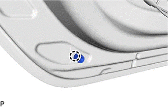
Engage the claw to install a new front door panel cushion.
-
- Click here
INSTALL FRONT DOOR NO. 2 WEATHERSTRIP
-
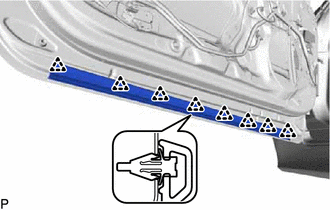
Engage the 8 clips to install the front door No. 2 weatherstrip.
-
- Click here
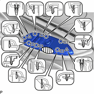
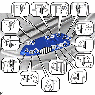
INSTALL FRONT DOOR WEATHERSTRIP
-
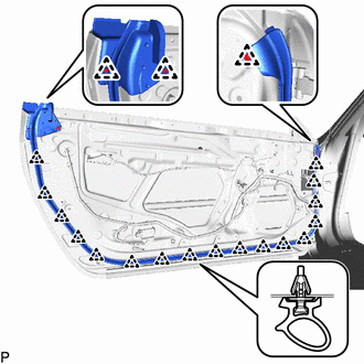
Engage the 20 clips to install the front door weatherstrip.
-
- Click here
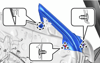
INSTALL FRONT DOOR CHECK ASSEMBLY
-
Apply MP grease to the sliding areas of the front door check assembly.
-
Clean the bolt hole on the vehicle body.
-
Clean the threads of the bolt.
-
Apply adhesive to the threads of the bolt.
Adhesive Toyota Genuine Adhesive 1324, Three Bond 1324 or equivalent -
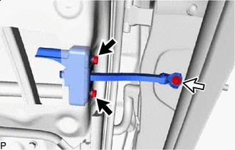

Nut 
Bolt Install the front door check assembly with the 2 nuts and bolt.
Nut 8.0 N*m 82 kgf*cm 71 in.*lbf Bolt 27 N*m 275 kgf*cm 20 ft.*lbf
-
- Click here
INSTALL FRONT DOOR VENT SEAL
-
Install the front door vent seal.
-
- Click here
INSTALL FRONT DOOR DIVISION BAR SEAL
-
Engage the claw.
-
Engage the 2 clips to install the front door division bar seal.
-
- Click here
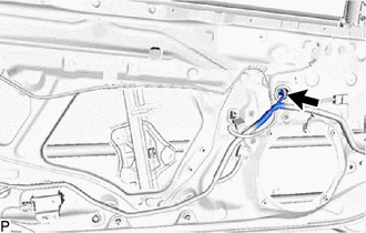
INSTALL DOOR GLASS FEMALE STABILIZER
-
Engage the 2 guides.
-
Install the door glass female stabilizer with the bolt.
11.5 N*m 117 kgf*cm 8 ft.*lbf
-
- Click here
INSTALL FRONT DOOR LOCK OPEN ROD
-
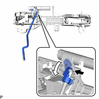
Install the front door lock open rod as indicated by the arrows, in the order shown in the illustration.
-
- Click here
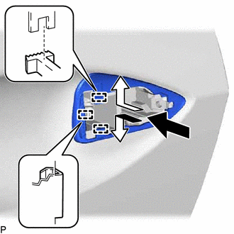
INSTALL FRONT DOOR OUTSIDE HANDLE FRAME SUB-ASSEMBLY
-
Apply MP grease to the sliding parts of the front door outside handle frame sub-assembly.
-
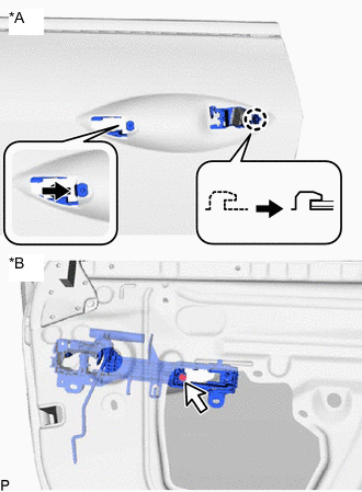
*A Outside *B Inside Engage the claw.
-
Using a T30 "TORX" socket wrench, install the front door outside handle frame sub-assembly with the screw.
4.0 N*m 41 kgf*cm 35 in.*lbf -
Engage the 3 clamps.
-
- Click here
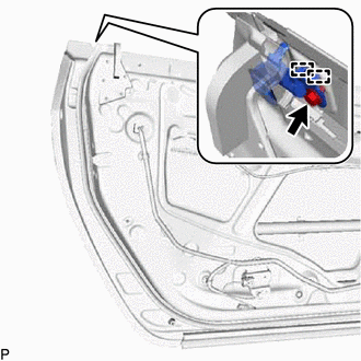
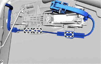
INSTALL FRONT DOOR LOCK WITH MOTOR ASSEMBLY
Note:
-
When reusing a removed front door lock with motor assembly, replace the door lock wire harness seal with a new one.
-
Do not allow grease or dust to adhere to the door lock wire harness seal installation surface.
-
Reusing a door lock wire harness seal or using a damaged door lock wire harness seal may cause water ingress. This may result in a malfunction of the front door lock with motor assembly.
-
Apply MP grease to the sliding parts of the front door lock with motor assembly.
-
When reusing the front door lock with motor assembly:
-
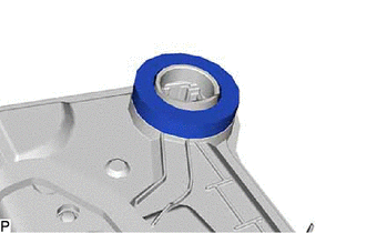
Install a new door lock wire harness seal to the front door lock with motor assembly.
-
-
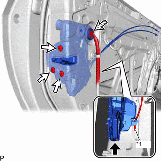
*1 Front Door Lock Open Rod Connect the front door lock open rod to the front door lock with motor assembly.
Tip:Make sure that the front door lock open rod is securely connected to the front door lock with motor assembly.
-
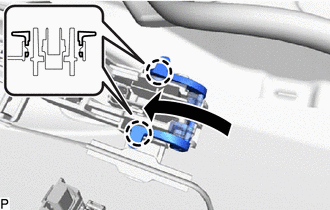
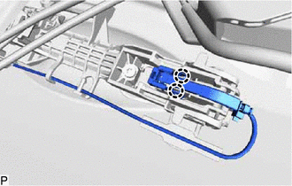
Using a T30 "TORX" socket wrench, install the front door lock with motor assembly with the 3 screws.
5.5 N*m 56 kgf*cm 49 in.*lbf -
Connect the connector.
-
- Click here
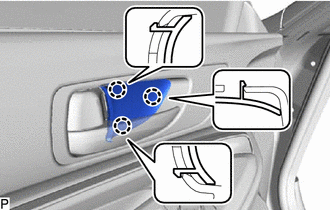
INSTALL FRONT DOOR REAR OUTSIDE HANDLE PAD
-
Engage the 3 guides as shown in the illustration.
-
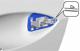
Engage the claw to install the front door rear outside handle pad.
-
- Click here
INSTALL FRONT DOOR OUTSIDE HANDLE PAD
-
Engage the 3 claws to install the front door outside handle pad.
-
- Click here
INSTALL FRONT DOOR OUTSIDE HANDLE COVER (for Front Passenger Side)
-
Engage the 2 guides and claw.
-
Using a T30 "TORX" socket wrench, install the front door outside handle cover with the screw.
4.0 N*m 41 kgf*cm 35 in.*lbf -
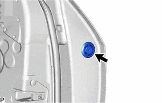
Install the hole plug.
-
- Click here
INSTALL FRONT DOOR LOCK CYLINDER ASSEMBLY (for Driver Side)
-
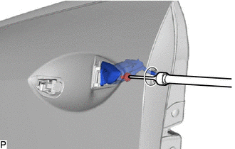
Using a T30 "TORX" socket wrench, install the front door lock cylinder assembly with the screw.
4.0 N*m 41 kgf*cm 35 in.*lbf -
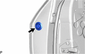
Install the hole plug.
-
- Click here
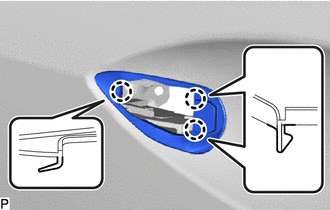
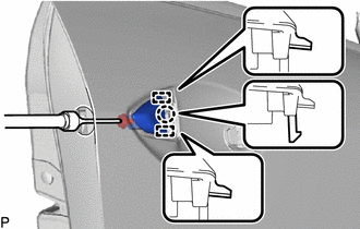
INSTALL FRONT DOOR OUTSIDE HANDLE ASSEMBLY
-
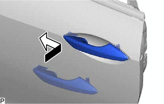
Insert the front end of the front door outside handle assembly into the front door outside handle frame sub-assembly.
-
Insert the rear end of the front door outside handle assembly into the front door outside handle frame sub-assembly, then slide the front door outside handle assembly toward the front of the vehicle to install it.
-
Move the lever as shown in the illustration and engage the 2 claws to lock the front door outside handle assembly.
-
Connect the connector.
-
Engage the 2 claws.
-
- Click here
INSTALL FRONT DOOR GLASS RUN
-
Engage the guide to install the front door glass run.
-
- Click here
INSTALL FRONT DOOR WINDOW REGULATOR ASSEMBLY
-
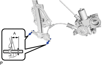
Using a 4 mm hexagon wrench, adjust the 2 stud bolts at the bottom of the front door window regulator assembly as shown in the illustration.
Table 1. Standard Clearance A 21.1 to 22.1 mm (0.831 to 0.870 in.) -
Apply MP grease to the sliding parts of the front door window regulator assembly.
-
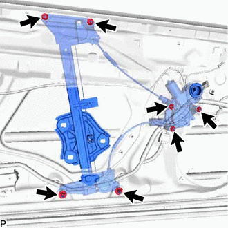
Temporarily install the front door window regulator assembly with the 7 nuts.
-
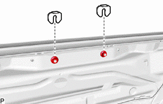
Install the 2 window regulator shims.
-
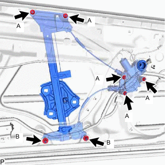
Tighten the 7 nuts to install the front door window regulator assembly.
Nut (A) 5.5 N*m 56 kgf*cm 49 in.*lbf Nut (B) 13 N*m 133 kgf*cm 10 ft.*lbf -
Connect the connector.
-
- Click here
INSTALL FRONT DOOR GLASS SUB-ASSEMBLY
-
Connect the cable to the negative (-) battery terminal.
-
for Driver Side:
-
Connect the multiplex network master switch assembly and move the front door window regulator assembly so that the door glass stud bolts can be seen.
-
-
for Front Passenger Side:
-
Connect the power window regulator switch assembly and move the front door window regulator assembly so that the door glass stud bolts can be seen.
-
-
Disconnect the cable from the negative (-) battery terminal.
-
for Driver Side:
-
Disconnect the multiplex network master switch assembly.
-
-
for Front Passenger Side:
-
Disconnect the power window regulator switch assembly.
-
-
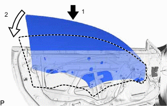
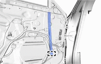
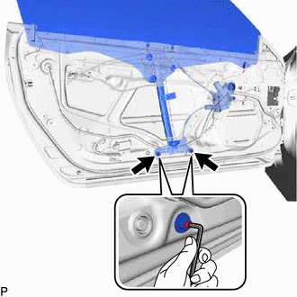
Insert the front door glass sub-assembly into the front door panel along the front door glass run as indicated by the arrows, in the order shown in the illustration.
-
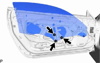
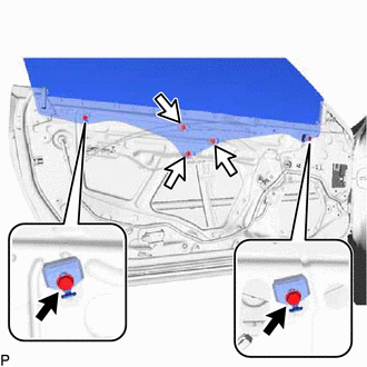
Install the front door glass sub-assembly with the 3 nuts.
8.0 N*m 82 kgf*cm 71 in.*lbf
-
- Click here
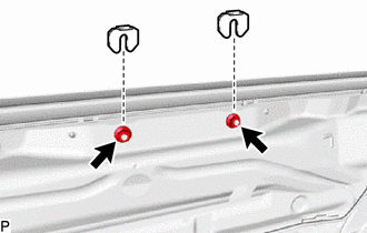
INSTALL FRONT DOOR UPPER WINDOW STOP
-
for Front Side:
-
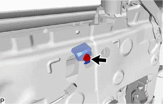
Install the front door upper window stop with the bolt.
11.5 N*m 117 kgf*cm 8 ft.*lbf
-
-
for Rear Side:
-
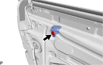
Install the front door upper window stop with the bolt.
11.5 N*m 117 kgf*cm 8 ft.*lbf
-
-
- Click here
INSPECT FRONT DOOR GLASS SUB-ASSEMBLY
-
Connect the cable to the negative (-) battery terminal.
-
for Driver Side:
-
Connect the multiplex network master switch assembly and fully close the front door glass sub-assembly.
-
-
for Front Passenger Side:
-
Connect the power window regulator switch assembly and fully close the front door glass sub-assembly.
-
-
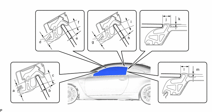
Check that the clearance measurements of areas a through m are within each standard range.
Table 2. Standard Clearance Area Measurement Area Measurement a 15.0 mm (0.591 in.) b 5.6 to 9.6 mm (0.220 to 0.378 in.) c 9.1 to 13.1 mm (0.358 to 0.516 in.) d 15.0 mm (0.591 in.) e 5.7 to 9.7 mm (0.224 to 0.382 in.) f 9.1 to 13.1 mm (0.358 to 0.516 in.) g 15.0 mm (0.591 in.) h 5.7 to 9.7 mm (0.224 to 0.382 in.) i 9.1 to 13.1 mm (0.358 to 0.516 in.) j 12.0 mm (0.472 in.) k 0 mm (0 in.) l 12.0 mm (0.472 in.) m 0 mm (0 in.) - - Note:Be careful not to cut the weatherstrip during door glass adjustment.
-
- Click here
ADJUST FRONT DOOR GLASS SUB-ASSEMBLY
-
Adjust the fit of the top part of the front door glass sub-assembly inward and outward.
-
Loosen the 2 nuts at the bottom of the front door window regulator assembly.
-
Using a 4 mm hexagon wrench, turn the 2 stud bolts to adjust the fit of the top part of the front door glass sub-assembly inward and outward.
Tip:When the stud bolt are turned counterclockwise, the top part of the front door glass sub-assembly moves toward the inside of the vehicle. When the stud bolt are turned clockwise, the top part of the front door glass sub-assembly moves toward the outside of the vehicle.
-
Tighten the 2 nuts after adjustment.
13 N*m 133 kgf*cm 10 ft.*lbf
-
-
Adjust the fit of the bottom part of the front door glass sub-assembly inward and outward.
-
Loosen the 2 nuts at the top of the front door window regulator assembly.
-
Change the number of installed window regulator shims to adjust the fit of the bottom part of the front door glass sub-assembly inward and outward.
Tip:When more shims are used, the bottom part of the front door glass sub-assembly moves toward the outside of the vehicle. When less shims are used, the bottom part of the front door glass sub-assembly moves toward the inside of the vehicle.
-
Tighten the 2 nuts after adjustment.
5.5 N*m 56 kgf*cm 49 in.*lbf
-
-
Adjust the front door glass sub-assembly fully closed position horizontally and vertically.
-
Loosen the 2 front door upper window stop bolts and temporarily move the front door upper window stops to the top of their adjustment range and then temporarily tighten the bolts.
-
Loosen the 3 front door glass sub-assembly nuts.
-
Stop the front door glass sub-assembly approximately 3 mm (0.118 in.) below the fully closed position.
-
While holding the front door glass sub-assembly, move it vertically and horizontally to adjust its position.
-
Tighten the 3 nuts after adjustment.
5.5 N*m 56 kgf*cm 49 in.*lbf -
Move the front door glass sub-assembly to the fully closed position.
-
Loosen the 2 front door upper window stop bolts.
-
While lightly pushing each front door upper window stop against the stopper on the front door glass sub-assembly, tighten each bolt.
15 N*m 153 kgf*cm 133 in.*lbf
-
-
for Driver Side:
-
Disconnect the multiplex network master switch assembly.
-
-
for Front Passenger Side:
-
Disconnect the power window regulator switch assembly.
-
-
Disconnect the cable from the negative (-) battery terminal.
-
- Click here
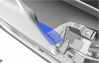
INSTALL FRONT DOOR SERVICE HOLE COVER
-
Apply new butyl tape to the front door panel.
-
Pass the front door lock remote control cable assembly and front door inside locking cable assembly through a new front door service hole cover.
-
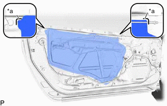
*a Reference Point Install the front door service hole cover according to the reference points on the front door panel.
Note:Securely install the front door service hole cover preventing wrinkles and air bubbles.
-
- Click here
INSTALL FRONT NO. 1 SPEAKER ASSEMBLY
- Click here
INSTALL FRONT DOOR TRIM BRACKET
-
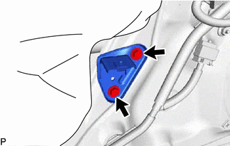
Install the front door trim bracket with the 2 screws.
-
- Click here
INSTALL FRONT DOOR LOWER FRAME BRACKET GARNISH
-
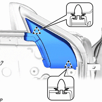
Engage the 2 clips to install the front door lower frame bracket garnish.
-
- Click here
INSTALL OUTER REAR VIEW MIRROR ASSEMBLY
- Click here
INSTALL OUTER MIRROR PROTECTOR
- Click here
INSTALL OUTER MIRROR INSTALL HOLE COVER
- Click here
INSTALL OUTER MIRROR CONTROL ECU ASSEMBLY
- Click here
INSTALL DOOR SIDE AIRBAG SENSOR
- Click here
INSTALL FRONT DOOR INNER GLASS WEATHERSTRIP
-
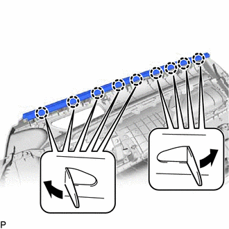
Engage the 9 claws to install the front door inner glass weatherstrip as shown in the illustration.
-
- Click here
INSTALL SEAT MEMORY SWITCH (w/ Memory)
- Click here
INSTALL FRONT DOOR INSIDE HANDLE SUB-ASSEMBLY
-
Install the front door inside handle sub-assembly with the 7 screws.
-
- Click here
INSTALL NO. 1 INTERIOR ILLUMINATION LIGHT ASSEMBLY
- Click here
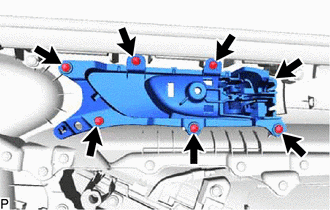
INSTALL FRONT DOOR TRIM BOARD SUB-ASSEMBLY
-
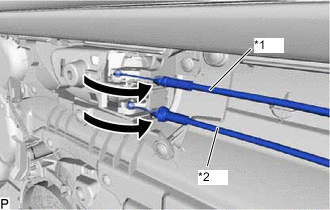
*1 Front Door Inside Locking Cable Assembly *2 Front Door Lock Remote Control Cable Assembly Connect the front door lock remote control cable assembly and front door inside locking cable assembly.
-
Connect each connector.
-
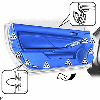
Engage the 9 clips to install the front door trim board sub-assembly as shown in the illustration.
-
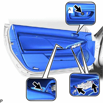
Install the 4 screws.
Screw (A) 3.5 N*m 36 kgf*cm 31 in.*lbf
-
- Click here
INSTALL FRONT DOOR NO. 1 STIFFENER CUSHION
-
Install the front door No. 1 stiffener cushion with the screw.
-
- Click here
INSTALL COURTESY LIGHT ASSEMBLY
- Click here
INSTALL DOOR TRIM COVER
-
Install the door trim cover.
-
- Click here
INSTALL MULTIPLEX NETWORK MASTER SWITCH ASSEMBLY WITH FRONT DOOR ARMREST BASE PANEL (for Driver Side)
-
Connect the connector.
-

Push Area Engage the 2 clips, 7 claws and 5 guides to install the multiplex network master switch assembly with front door armrest base panel.
-
Press the push area.
Tip:Check that the front door armrest base panel are attached to the front door trim board sub-assembly correctly.
-
- Click here
INSTALL POWER WINDOW REGULATOR SWITCH ASSEMBLY WITH FRONT DOOR ARMREST BASE PANEL (for Front Passenger Side)
-
Connect the connector.
-
Push Area Engage the 2 clips, 7 claws and 5 guides to install the power window regulator switch assembly with front door armrest base panel.
-
Press the push area.
Tip:Check that the front door armrest base panel are attached to the front door trim board sub-assembly correctly.
-
- Click here
INSTALL FRONT DOOR INSIDE HANDLE BEZEL PLUG
-
Engage the 3 claws to install the front door inside handle bezel plug.
-
- Click here
CONNECT CABLE TO NEGATIVE BATTERY TERMINAL
Note:When disconnecting the cable, some systems need to be initialized after the cable is reconnected.
- Click here
INITIALIZE POWER WINDOW CONTROL SYSTEM
- Click here
INSPECT POWER WINDOW OPERATION
- Click here
INSPECT SRS WARNING LIGHT