PROCEDURE
- Click here
INSTALL SLIDING ROOF HOUSING ASSEMBLY
-
Loosen the 6 bolts from the bracket of the sliding roof housing assembly.
-
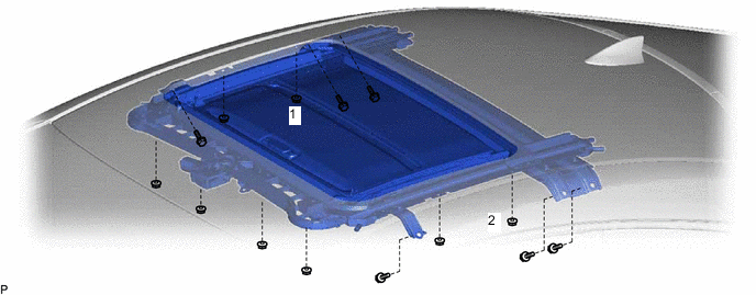
Temporarily install the sliding roof housing assembly with the 8 nuts and 6 bolts.
-
Tighten the 2 nuts.
Tip:Tighten the 2 nuts in the order shown in the illustration.
15 N*m 153 kgf*cm 11 ft.*lbf -
Tighten the 6 nuts.
15 N*m 153 kgf*cm 11 ft.*lbf -
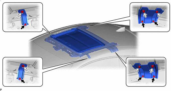

Bolt (A) 
Bolt (B) Tighten the 12 bolts to install the sliding roof housing assembly.
Bolt (A) 8.0 N*m 82 kgf*cm 71 in.*lbf Bolt (B) 15 N*m 153 kgf*cm 11 ft.*lbf Tip:The brackets can be installed in any order. The bolts must be tightened in the order of (A) then (B).
-
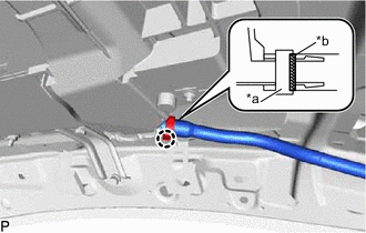
*a Clamp *b Marking for Clamp Type:
-
Connect the sliding roof drain hose.
Tip:Slide the hose to the base of the drain pipe.
-
Engage the claw to secure the sliding roof drain hose.
Tip:
-
Make sure that the clamp is on the marking or between the marking and hose end.
-
Use the same procedure for the other 3 sliding roof drain hoses.
-
-
-
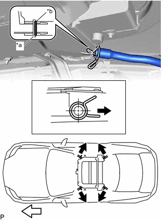
*a Clip *b Marking Outside Front Side for Clip Type:
-
Expand the clip to connect the sliding roof drain hose.
Tip:Slide the hose to the base of the drain pipe.
-
Release the clip to secure the sliding roof drain hose.
Note:The clip must face toward the outside of the vehicle and also be above the lower surface of the sliding roof housing sub-assembly when installing the drain hoses.
Tip:
-
Make sure that the clip is on the marking or between the marking and hose end.
-
Use the same procedure for the other 3 sliding roof drain hoses.
-
-
-
- Click here
INSTALL SLIDING ROOF WEATHERSTRIP
-
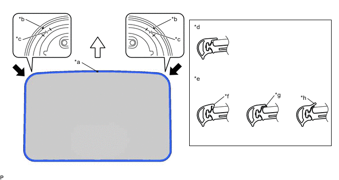
*a Joint *b Alignment Mark (Purple) *c Middle Mark *d Correct *e Incorrect *f Pinched *g Exposed *h Gap (raised, wavy, etc.) Front Side - - Install the sliding roof weatherstrip:
-
Position the joint of the sliding roof weatherstrip at the front center.
-
Align the alignment marks (purple) on the sliding roof weatherstrip with the middle marks at the corners of the sliding roof panel sub-assembly and install the sliding roof weatherstrip.
-
Install the lip of the sliding roof weatherstrip firmly.
-
-
- Click here
INSTALL SLIDING ROOF GLASS SUB-ASSEMBLY
-
Using a T25 "TORX" socket wrench, temporarily install the sliding roof glass sub-assembly with the 4 screws.
-
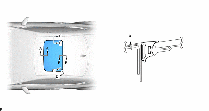
Perform a level check.
-
Check the difference in level "a" between the roof panel and the upper surface of the sliding roof weatherstrip when the sliding roof glass sub-assembly is fully closed.
Tip:"+" represents the condition that the glass is above the panel level. "-" represents the condition that the glass is below the panel level.
Standard Area Measurement Area Measurement A - A 0 + 1.0 mm (0 + 0.0394 in.)
0 - 2.0 mm (0 - 0.0787 in.)
B - B 0 + 2.0 mm (0 + 0.0787 in.)
0 - 1.0 mm (0 - 0.0394 in.)
C - C 0 + 1.5 mm (0 + 0.0591 in.)
0 - 1.5 mm (0 - 0.0591 in.)
D - D 0 + 1.5 mm (0 + 0.0591 in.)
0 - 1.5 mm (0 - 0.0591 in.)
-
-
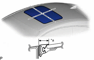
*a Even Perform a gap check.
-
Check the gap between the roof panel and sliding roof glass sub-assembly.
Note:The gap must be even all around.
-
-
- Click here
CHECK FOR WATER LEAK
-
After adjusting the sliding roof glass sub-assembly, check for water leakage into the vehicle interior.
-
If there are any leaks, readjust the sliding roof glass sub-assembly.
-
- Click here
INSTALL CURTAIN SHIELD AIRBAG ASSEMBLY LH
- Click here
INSTALL CURTAIN SHIELD AIRBAG ASSEMBLY RH
Tip:Use the same procedure as for the LH side.
- Click here
INSTALL NO. 1 SLIDING ROOF SIDE GARNISH LH
-
Press and hold the UP switch until the sliding roof glass sub-assembly is fully tilted up.
-
Engage the 3 claws to install the No. 1 sliding roof side garnish LH.
-
- Click here
INSTALL NO. 1 SLIDING ROOF SIDE GARNISH RH
Tip:Use the same procedure as for the LH side.
- Click here
INSTALL NO. 2 SLIDING ROOF SIDE GARNISH LH
-
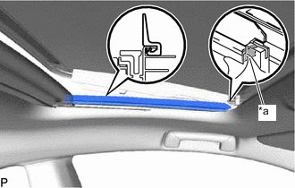
*a Shaded Portion Align the front of the No. 2 sliding roof side garnish LH with the shaded portion, and then install the No. 2 sliding roof side garnish LH.
-
- Click here
INSTALL NO. 2 SLIDING ROOF SIDE GARNISH RH
Tip:Use the same procedure as for the LH side.
- Click here
RESET SLIDING ROOF DRIVE GEAR SUB-ASSEMBLY
- Click here
CHECK SLIDING ROOF SYSTEM