| DTC Code | DTC Name |
|---|---|
| Windshield Deicer does not Operate |
DESCRIPTION
When the front wiper deicer switch is operated, the operation signal is transmitted to the air conditioning amplifier assembly directly. When the air conditioning amplifier assembly receives the signal, it turns on the semiconductor pwr integration ECU to operate the windshield deicer system.
CAUTION / NOTICE / HINT
-
Inspect the fuses for circuits related to this system before performing the following procedure.
-
If the battery voltage is low, the windshield deicer system may not operate. When "Operation of Electrical Items Restricted." is not displayed on the multi-information display in the combination meter assembly, check the Data List item "Battery Control Count (Body ECU)".
PROCEDURE
- Click here
PERFORM ACTIVE TEST USING GTS
-
Connect the GTS to the DLC3.
-
Turn the engine switch on (IG).
-
Turn the GTS on.
-
Enter the following menus: Body Electrical / Air Conditioner / Active Test.
-
Perform the Active Test according to the display on the GTS.
- Body Electrical > Air Conditioner > Active Test
Tester Display Measurement Item Control Range Diagnostic Note Deicer Relay (Front) Windshield glass (windshield deicer wire) OFF or ON - -
-
- Body Electrical > Air Conditioner > Active Test
Tester Display Deicer Relay (Front) -
-
-
-
OK The windshield deicer system operates normally. Result Proceed to OK NG - Body Electrical > Air Conditioner > Active Test
- OKClick here
- NGClick here
-
- Click here
INSPECT FRONT WIPER DEICER SWITCH
-
Remove the front wiper deicer switch.
-
Inspect the front wiper deicer switch.
Result Proceed to OK NG
- OKClick here
- NG
REPLACE FRONT WIPER DEICER SWITCHClick here
-
- Click here
CHECK HARNESS AND CONNECTOR (FRONT WIPER DEICER SWITCH - IG POWER SUPPLY)
-
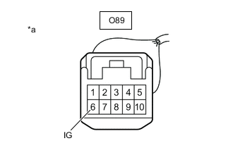
*a Front view of wire harness connector
(to Front Wiper Deicer Switch)
Measure the voltage according to the value(s) in the table below.
Standard Voltage Tester Connection Condition Specified Condition O89-6 (IG) - Body ground Engine switch off Below 1 V O89-6 (IG) - Body ground Engine switch on (IG) 11 to 14 V Result Proceed to OK NG
- OKClick here
- NG
REPAIR OR REPLACE HARNESS OR CONNECTOR
-
- Click here
CHECK HARNESS AND CONNECTOR (FRONT WIPER DEICER SWITCH - AIR CONDITIONING AMPLIFIER ASSEMBLY)
-
Disconnect the O9 and O10 air conditioning amplifier assembly connectors.
-
Measure the resistance according to the value(s) in the table below.
Standard Resistance Tester Connection Condition Specified Condition O89-10 (IND-) - O9-17 (SWL2) Always Below 1 Ω O89-10 (IND-) or O9-17 (SWL2) - Body ground Always 10 kΩ or higher O89-9 (ECU) - O10-28 (SW6) Always Below 1 Ω O89-9 (ECU) or O10-28 (SW6) - Body ground Always 10 kΩ or higher Result Proceed to OK NG
- OK
REPLACE AIR CONDITIONING AMPLIFIER ASSEMBLYClick here
- NG
REPAIR OR REPLACE HARNESS OR CONNECTOR
-
- Click here
CHECK SEMICONDUCTOR POWER INTEGRATION ECU
-
Using a voltmeter, check the signal reading of the semiconductor pwr integration ECU.
OK Output signal reading is normal. Result Proceed to OK NG
- OKClick here
- NG
INSPECT SEMICONDUCTOR POWER INTEGRATION ECU (RESULTS OF SIGNAL READING CHECK)Click here
-
- Click here
CHECK HARNESS AND CONNECTOR (SEMICONDUCTOR PWR INTEGRATION ECU POWER SOURCE AND BODY GROUND)
-
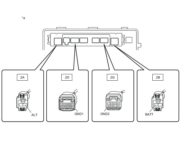
*a Component without semiconductor pwr integration ECU
(No. 2 Engine Room Relay Block and No. 2 Junction Block Assembly)
- - Remove the semiconductor pwr integration ECU from the No. 2 engine room relay block and No. 2 junction block assembly.
-
Measure the voltage according to the value(s) in the table below.
Standard Voltage Tester Connection Condition Specified Condition 2B-1 (BATT) - Body ground Always 11 to 14 V 2A-1 (ALT) - Body ground Always 11 to 14 V -
Measure the resistance according to the value(s) in the table below.
Standard Resistance Tester Connection Condition Specified Condition 2D-14 (GND1) - Body ground Always Below 1 Ω 2G-5 (GND2) - Body ground Always Below 1 Ω Result Proceed to OK NG
- OKClick here
- NG
REPAIR OR REPLACE HARNESS OR CONNECTOR
-
- Click here
CHECK HARNESS AND CONNECTOR (AIR CONDITIONING AMPLIFIER ASSEMBLY - SEMICONDUCTOR PWR INTEGRATION ECU)
-
Disconnect the O9 air conditioning amplifier assembly connector.
-
Measure the resistance according to the value(s) in the table below.
Standard Resistance Tester Connection Condition Specified Condition O9-24 (FDEF) - 2D-6 (-S) Always Below 1 Ω O9-24 (FDEF) or 2D-6 (-S) - Body ground Always 10 kΩ or higher Result Proceed to OK NG
- OKClick here
- NG
REPAIR OR REPLACE HARNESS OR CONNECTOR
-
- Click here
CHECK SEMICONDUCTOR POWER INTEGRATION ECU
-
Install the semiconductor pwr integration ECU.
-
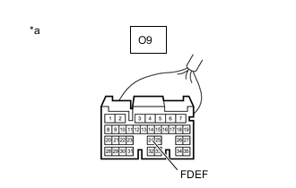
*a Front view of wire harness connector
(to Air Conditioning Amplifier Assembly)
Measure the voltage according to the value(s) in the table below.
Standard Voltage Tester Connection Condition Specified Condition O9-24 (FDEF) - Body ground Engine switch on (IG), Front wiper deicer switch off 11 to 14 V Result Proceed to OK NG
- OKClick here
- NG
REPLACE SEMICONDUCTOR POWER INTEGRATION ECUClick here
-
- Click here
CHECK AIR CONDITIONING AMPLIFIER ASSEMBLY
-
Reconnect the O9 air conditioning amplifier assembly connector.
-
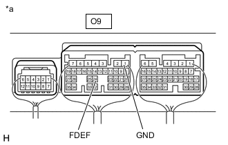
*a Component with harness connected
(Air Conditioning Amplifier Assembly)
Measure the voltage according to the value(s) in the table below.
Standard Voltage Tester Connection Condition Specified Condition O9-24 (FDEF) - O9-1 (GND) Engine switch on (IG), Front wiper deicer switch on Below 2.2 V O9-24 (FDEF) - O9-1 (GND) Engine switch on (IG), Front wiper deicer switch off 11 to 14 V Result Proceed to OK NG
- OKClick here
- NG
REPLACE AIR CONDITIONING AMPLIFIER ASSEMBLYClick here
-
- Click here
CHECK HARNESS AND CONNECTOR (SEMICONDUCTOR PWR INTEGRATION ECU - WINDSHIELD GLASS (WINDSHIELD DEICER WIRE))
-
Disconnect the 2E semiconductor pwr integration ECU connector.
-
Disconnect the A74 windshield glass (windshield deicer wire) connector.
-
Measure the resistance according to the value(s) in the table below.
Standard Resistance Tester Connection Condition Specified Condition 2E-8 (L) - A74-1 (B2) Always Below 1 Ω 2E-8 (L) - A74-2 (B) Always Below 1 Ω Result Proceed to OK NG
- OKClick here
- NG
REPAIR OR REPLACE HARNESS OR CONNECTOR
-
- Click here
CHECK SEMICONDUCTOR POWER INTEGRATION ECU
-
Reconnect the 2E semiconductor pwr integration ECU connector.
-
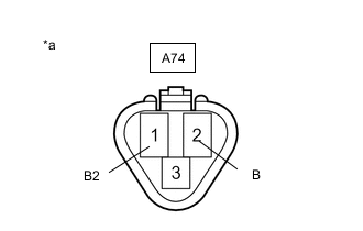
*a Front view of wire harness connector
(to Windshield Glass (Windshield Deicer Wire))
Measure the voltage according to the value(s) in the table below.
Standard Voltage Tester Connection Condition Specified Condition A74-1 (B2) - Body ground Engine switch on (IG), Front wiper deicer switch off Below 1 V A74-1 (B2) - Body ground Engine switch on (IG), Front wiper deicer switch on 11 to 14 V A74-2 (B) - Body ground Engine switch on (IG), Front wiper deicer switch off Below 1 V A74-2 (B) - Body ground Engine switch on (IG), Front wiper deicer switch on 11 to 14 V Result Proceed to OK NG
- OKClick here
- NG
REPLACE SEMICONDUCTOR POWER INTEGRATION ECUClick here
-
- Click here
CHECK HARNESS AND CONNECTOR (WINDSHIELD GLASS (WINDSHIELD DEICER WIRE) - BODY GROUND)
-
Measure the resistance according to the value(s) in the table below.
Standard Resistance Tester Connection Condition Specified Condition A74-3 (E) - Body ground Always Below 1 Ω Result Proceed to OK NG
- OK
REPLACE WINDSHIELD GLASS (WINDSHIELD DEICER WIRE)Click here
- NG
REPAIR OR REPLACE HARNESS OR CONNECTOR
-