CAUTION / NOTICE / HINT
-
When replacing the windshield glass of a vehicle equipped with a lane departure warning camera, make sure to use a Lexus genuine part. If a non-Lexus genuine part is used, the lane departure warning camera may not be able to be installed due to a missing bracket or the lane departure alert system may not operate properly due to a difference in the transmissivity or black ceramic border.
-
Make sure to use Toyota Genuine Windshield Glass Adhesive (High Modulus Type) or equivalent.
PROCEDURE
- Click here
INSTALL NO. 1 WINDSHIELD GLASS STOPPER (for 2-piece Type)
-
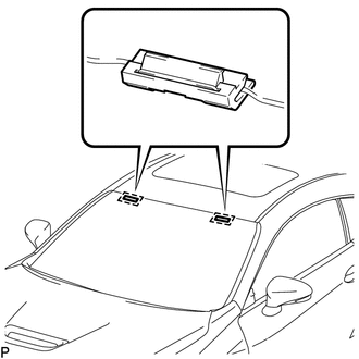
Install 2 new No. 1 windshield glass stoppers to the vehicle body as shown in the illustration.
Tip:Only 2-piece type windshield glass stoppers are provided as supply parts. Use 2-piece type stoppers as replacements even if 1-piece type stoppers were originally installed.
-
- Click here
INSTALL NO. 2 WINDSHIELD GLASS STOPPER (for 2-piece Type)
-
Using a brush or sponge, coat the installation area of 2 new No. 2 windshield glass stoppers with primer G.
Note:
-
Do not apply too much primer G.
-
Allow the primer G to dry for 3 minutes or more.
-
Throw away any leftover primer G.
Tip:If an area other than specified is coated by accident, wipe off the primer G with a clean piece of cloth before it dries.
-
-
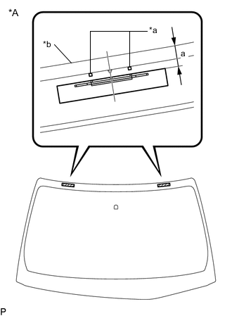
*A Back Side *a Ceramic Notch *b Windshield Glass Edge Side Install the 2 new No. 2 windshield glass stoppers to the windshield glass as shown in the illustration.
Standard Dimension Area Dimension a 14.2 mm (0.559 in.) Tip:Only 2-piece type windshield glass stoppers are provided as supply parts. Use 2-piece type stoppers as replacements even if 1-piece type stoppers were originally installed.
-
- Click here
INSTALL WINDSHIELD OUTSIDE MOULDING
-
Using a brush or sponge, coat the installation area of a new windshield outside moulding with primer G.
Note:
-
Do not apply too much primer G.
-
Allow the primer G to dry for 3 minutes or more.
-
Throw away any leftover primer G.
Tip:If an area other than specified is coated by accident, wipe off the primer G with a clean piece of cloth before it dries.
-
-
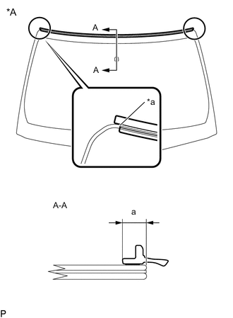
*A Back Side *a Edge Of Curved Surface Install the new windshield outside moulding to the windshield glass as shown in the illustration.
Standard Dimension Area Dimension a 7.15 mm (0.281 in.)
-
- Click here
INSTALL NO. 1 INSTRUMENT PANEL CUSHION
-
Using a brush or sponge, coat the installation area of a new No. 1 instrument panel cushion with primer G.
Note:
-
Do not apply too much primer G.
-
Allow the primer G to dry for 3 minutes or more.
-
Throw away any leftover primer G.
Tip:If an area other than specified is coated by accident, wipe off the primer G with a clean piece of cloth before it dries.
-
-
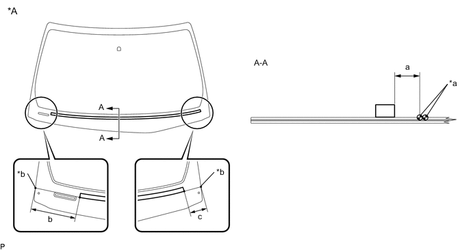
*A Back Side - - *a Ceramic Notch *b Windshield Glass Edge Side Install the new No. 1 instrument panel cushion to the windshield glass as shown in the illustration.
Standard Dimension Area Dimension a 102.5 mm (4.04 in.) b 174.1 mm (6.85 in.) c 74.3 mm (2.93 in.)
-
- Click here
INSTALL FRONT WINDOW INNER MOULDING COVER LH
-
Using a brush or sponge, coat the installation area of a new front window inner moulding cover LH with primer G.
Note:
-
Do not apply too much primer G.
-
Allow the primer G to dry for 3 minutes or more.
-
Throw away any leftover primer G.
Tip:If an area other than specified is coated by accident, wipe off the primer G with a clean piece of cloth before it dries.
-
-
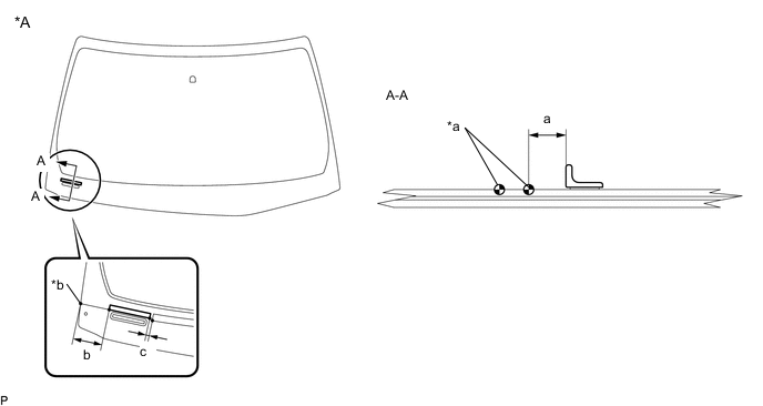
*A Back Side - - *a Ceramic Notch *b Windshield Glass Edge Side Install the new front window inner moulding cover LH to the windshield glass as shown in the illustration.
Standard Dimension Area Dimension a 9.0 mm (0.354 in.) b 69.6 mm (2.74 in.) c 5.0 mm (0.197 in.)
-
- Click here
INSTALL WINDOW GLASS ADHESIVE DAM
-
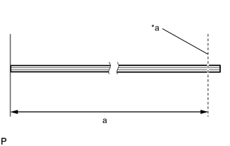
*a Cut Cut a new window glass adhesive dam so that it is the appropriate size as shown in the illustration.
Standard Dimension Area Dimension a 2762 mm (109 in.) -
Using a brush or sponge, coat the installation area of the new window glass adhesive dam with primer G.
Note:
-
Do not apply too much primer G.
-
Allow the primer G to dry for 3 minutes or more.
-
Throw away any leftover primer G.
Tip:If an area other than specified is coated by accident, wipe off the primer G with a clean piece of cloth before it dries.
-
-
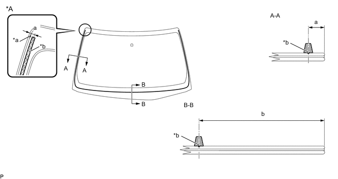
*A Back Side - - *a window glass adhesive dam positioning ceramic notch *b window glass adhesive dam positioning center line Install the window glass adhesive dam to the windshield glass as shown in the illustration.
Standard Dimension Area Dimension a 11.5 mm (0.453 in.) b 89.0 mm (3.50 in.)
-
- Click here
INSTALL WINDSHIELD GLASS SUB-ASSEMBLY
-
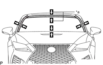
*a Matchmark Position the windshield glass sub-assembly.
-
Using suction cups, place the windshield glass sub-assembly in the correct position.
-
Check that the whole contact surface of the windshield glass sub-assembly rim is perfectly even.
-
Align the matchmarks on the windshield glass sub-assembly and vehicle body.
Note:Check that the windshield glass stoppers are engaged to the vehicle body correctly.
-
Remove the windshield glass sub-assembly.
-
-
Using a brush, coat the installation surface on the vehicle body with primer M.
Note:
-
Do not coat the adhesive with primer M.
-
Do not apply too much primer M.
-
Allow the primer M to dry for 3 minutes or more.
-
Throw away any leftover primer M.
Tip:If an area other than specified is coated by accident, wipe off the primer M with a clean piece of cloth before it dries.
-
-
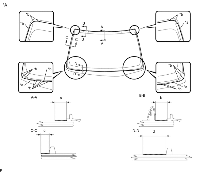
*A Back Side - - *a Adhesive center position *b Ceramic Notch 
Primer G - - Using a brush or sponge, coat the application area of adhesive with primer G.
Standard Dimension Area Dimension a 11.0 mm (0.433 in.) b 8.3 mm (0.327 in.) c 6.5 mm (0.256 in.) d 19.0 mm (0.748 in.) Note:
-
Do not apply too much primer G.
-
Allow the primer G to dry for 3 minutes or more.
-
Throw away any leftover primer G.
Tip:
-
Apply primer G onto the ceramic notches.
-
If an area other than specified is coated by accident, wipe off the primer G with a clean piece of cloth before it dries.
-
-
Apply adhesive to the windshield glass sub-assembly.
Adhesive Toyota Genuine Windshield Glass Adhesive (High modulus Type) or Equivalent
-
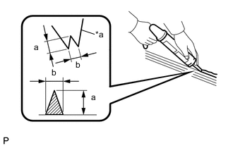
*a Nozzle Cut off the tip of the cartridge nozzle as shown in the illustration.
Standard Dimension Area Dimension a 12.0 mm (0.472 in.) or more b 8.0 mm (0.315 in.) or more -
Load the sealer gun with the cartridge.
-
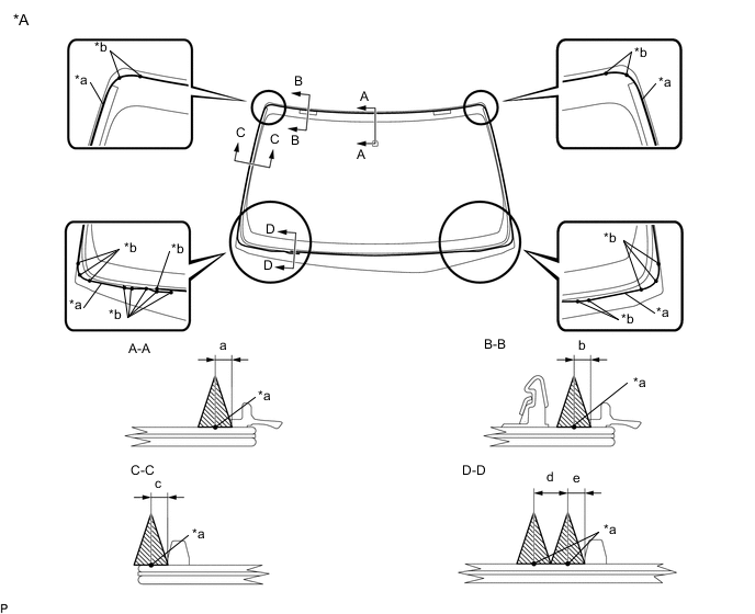
*A Back Side - - *a Adhesive center position *b Ceramic Notch Adhesive - - Apply adhesive to the windshield glass sub-assembly as shown in the illustration.
Standard Dimension Area Dimension a 4.0 mm (0.157 in.) b 4.0 mm (0.157 in.) c 4.0 mm (0.157 in.) d 8.0 mm (0.315 in.) e 4.0 mm (0.157 in.) Tip:Apply adhesive onto the ceramic notches.
-
-
*a Matchmark Install the windshield glass sub-assembly.
-
Using suction cups, position the windshield glass sub-assembly so that the matchmarks are aligned, and press it in gently along the rim.
Note:
-
Check that the windshield glass stoppers are engaged to the vehicle body correctly.
-
Check the clearance between the vehicle body and windshield glass sub-assembly.
-
-
Lightly press the front surface of the windshield glass sub-assembly to ensure that the windshield glass is securely fit to the vehicle body.
Tip:Press the glass with a force of 98 N (10 kgf, 22.0 lbf) or more.
-
Using a scraper, remove any excess or protruding adhesive.
-
Hold the windshield glass using protective tape until the applied adhesive becomes hard.
Note:Do not drive the vehicle for the time described in the table below.
Minimum Time Temperature Minimum Time Prior to Driving Vehicle 35°C (95°F) 1 hour and 30 minutes 20°C (68°F) 5 hours 5°C (41°F) 24 hours
-
-
w/ Windshield Deicer System:
-
Connect the connector.
-
-
- Click here
INSPECT FOR LEAK
-
After the adhesive has hardened, apply water from the outside of the vehicle. Check that no water leaks into the cabin.
-
If water leaks into the cabin, allow the water to dry and add adhesive.
-
Remove the protective tape.
-
- Click here
INSTALL ROOF HEADLINING ASSEMBLY
- Click here
INSTALL LANE DEPARTURE WARNING CAMERA (w/ Lane Departure Alert System)
- Click here
INSTALL RAIN SENSOR (w/ Rain Sensor)
- Click here
INSTALL INNER REAR VIEW MIRROR ASSEMBLY
- Click here
INSTALL COWL TOP VENTILATOR LOUVER SUB-ASSEMBLY
- Click here
INSTALL COWL TOP SILENCER PAD LH
- Click here
INSTALL COWL TOP SILENCER PAD RH
- Click here
INSTALL FRONT WIPER ARM AND BLADE ASSEMBLY LH
- Click here
INSTALL FRONT WIPER ARM AND BLADE ASSEMBLY RH
- Click here
INSTALL FRONT WIPER ARM HEAD CAP
- Click here
INSTALL WINDSHIELD OUTSIDE MOULDING LH
- Click here
INSTALL WINDSHIELD OUTSIDE MOULDING RH
Tip:Use the same procedure as for the LH side.