ROOF HEADLINING REMOVAL

PROCEDURE
-
REMOVE FRONT SEAT ASSEMBLY LH
-
REMOVE FRONT SEAT ASSEMBLY RH
Tech Tips
Use the same procedure as for the LH side.
-
REMOVE FRONT DOOR SCUFF PLATE LH
-
Disengage the 2 claws (A).
-
Disengage the 10 claws (B) and 5 guides to remove the front door scuff plate LH.
-
-
REMOVE FRONT DOOR OPENING TRIM COVER LH
-
Disengage the 3 claws (A) and guide (A).
Tech Tips
Disengage the claws and guide from the lower side of the front door opening trim cover LH.
-
Disengage the claw (B) and guide (B) to remove the front door opening trim cover LH.
-
-
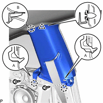
REMOVE FRONT PILLAR GARNISH LH
-
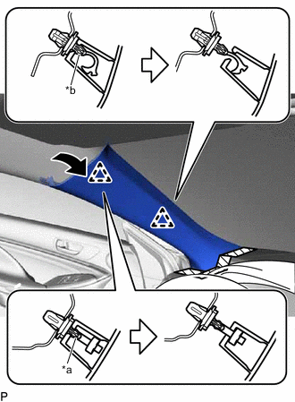
*a Front Pillar Garnish Clip (A) *b Front Pillar Garnish Clip (B) 
Protective Tape Apply protective tape around the front pillar garnish LH as shown in the illustration.
-
Pull the upper part of the front pillar garnish LH toward the inside of the cabin and disengage the front pillar garnish LH from the base of the 2 front pillar garnish clips.
Tech Tips
Let the front pillar garnish LH hang from the 2 front pillar garnish clips.
-
While pushing the tabs on the 2 front pillar garnish clips as shown in the illustration, disengage the 2 front pillar garnish clips.
Note
-
A front pillar garnish clip is reusable if it is not damaged.
-
Do not apply excessive force using a tool.
-
-
Disengage the 3 guides to remove the front pillar garnish LH as shown in the illustration.
-
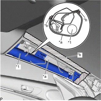
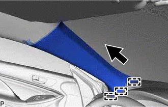
*1 Curtain Shield Airbag Assembly LH *a Protective Cover *b Adhesive Tape Protect the curtain shield airbag assembly LH.
-
Cover the curtain shield airbag assembly LH with a piece of cloth or nylon and secure the edges of the cover with tape as shown in the illustration.
Note
Cover the curtain shield airbag assembly LH with a protective cover as soon as the front pillar garnish LH is removed.
-
-
-
REMOVE FRONT DOOR SCUFF PLATE RH
Tech Tips
Use the same procedure as for the LH side.
-
REMOVE FRONT DOOR OPENING TRIM COVER RH
Tech Tips
Use the same procedure as for the LH side.
-
REMOVE FRONT PILLAR GARNISH RH
Tech Tips
Use the same procedure as for the LH side.
-
REMOVE REAR SEAT CUSHION ASSEMBLY
-
REMOVE REAR SEAT CUSHION LOCK HOOK
-
REMOVE LAP BELT OUTER ANCHOR COVER (for LH Side)
-
DISCONNECT FRONT SEAT OUTER BELT ASSEMBLY LH
-
DISCONNECT REAR SEAT 3 POINT TYPE OUTER BELT ASSEMBLY LH
-
REMOVE REAR SIDE SEATBACK ASSEMBLY LH
-
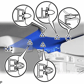
REMOVE FRONT QUARTER TRIM PANEL ASSEMBLY LH
-
Remove the bolt and disconnect the belt guide of the rear seat 3 point type outer belt assembly LH.
-
Remove the 2 clips.
*A w/o Rear No. 2 Speaker Assembly *B w/ Rear No. 2 Speaker Assembly -
Disengage the 4 clips (A).
-
Disengage the 7 claws, 3 clips (B) and guide to disconnect the front quarter trim panel assembly LH.
Tech Tips
Disengage the claws, clips and guide from the front side of the front quarter trim panel assembly LH.
-
Disengage the clamp.
-
Disconnect the connector to remove the front quarter trim panel assembly LH.
-
-
REMOVE CENTER PILLAR GARNISH ASSEMBLY LH
-
Remove the 2 screws.
-
Disengage the 2 claws (A).
-
Disengage the claw (B) and clip to disconnect the center pillar garnish assembly LH.
-
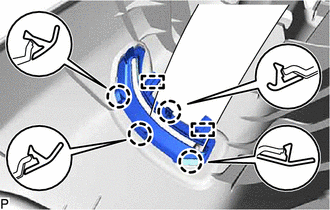
Disengage the 4 claws and 2 guides to disconnect the belt guide of the front seat outer belt assembly LH.
-
Pass the floor anchor of the front seat outer belt assembly LH through the center pillar garnish assembly LH to remove it.
-
-
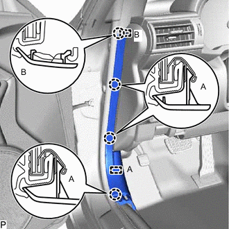
REMOVE INNER ROOF SIDE GARNISH ASSEMBLY LH
-
Disengage the claw and 4 clips.
-
Disengage the guide to remove the inner roof side garnish assembly LH.
-
-
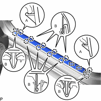
REMOVE ROOF SIDE RAIL GARNISH ASSEMBLY LH
-
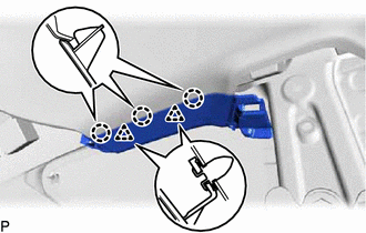
Disengage the 3 claws and 2 clips to remove the roof side rail garnish assembly LH.
Tech Tips
Disengage the claws and clips from the front side of the roof side rail garnish assembly LH.
-
-
REMOVE LAP BELT OUTER ANCHOR COVER (for RH Side)
Tech Tips
Use the same procedure as for the LH side.
-
DISCONNECT FRONT SEAT OUTER BELT ASSEMBLY RH
Tech Tips
Use the same procedure as for the LH side.
-
DISCONNECT REAR SEAT 3 POINT TYPE OUTER BELT ASSEMBLY RH
Tech Tips
Use the same procedure as for the LH side.
-
REMOVE REAR SIDE SEATBACK ASSEMBLY RH
Tech Tips
Use the same procedure as for the LH side.
-
REMOVE FRONT QUARTER TRIM PANEL ASSEMBLY RH
Tech Tips
Use the same procedure as for the LH side.
-
REMOVE CENTER PILLAR GARNISH ASSEMBLY RH
Tech Tips
Use the same procedure as for the LH side.
-
REMOVE INNER ROOF SIDE GARNISH ASSEMBLY RH
Tech Tips
Use the same procedure as for the LH side.
-
REMOVE ROOF SIDE RAIL GARNISH ASSEMBLY RH
Tech Tips
Use the same procedure as for the LH side.
-
REMOVE INSTRUMENT PANEL SAFETY PAD SUB-ASSEMBLY
-
REMOVE INNER REAR VIEW MIRROR STAY HOLDER COVER (w/ Cover)
-
REMOVE RAIN SENSOR COVER (w/ Rain Sensor)
-
REMOVE RAIN SENSOR (w/ Rain Sensor)
-
REMOVE NO. 2 FORWARD RECOGNITION COVER (w/ Pre-collision System)
-
REMOVE NO. 1 FORWARD RECOGNITION COVER (w/ Pre-collision System)
-
REMOVE MAP LIGHT ASSEMBLY
-
REMOVE NO. 1 ROOM LIGHT ASSEMBLY
-
REMOVE ASSIST GRIP SUB-ASSEMBLY (for LH Side)
-
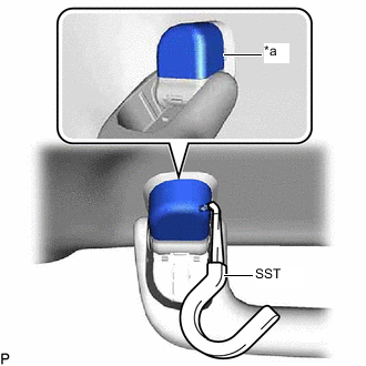
*a Cutout Insert SST into the cutout of the assist grip cover as shown in the illustration.
- SST
- 09813-00010
Note
To prevent the assist grip sub-assembly from being damaged, make sure to insert SST straight into the cutout.
-
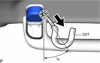
*a 30 to 45° 
Pull in this Direction Pull SST as shown in the illustration to disengage the claw.
Note
To prevent the assist grip sub-assembly from being damaged, make sure to only pull SST as shown in the illustration.
Tech Tips
Use the same procedure for the claw on the other side of the assist grip cover.
-
Remove the assist grip cover.
Tech Tips
Use the same procedure for the LH side and RH side.
-
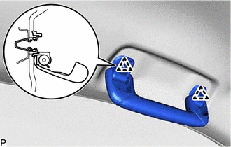
Disengage the 2 clips and remove the assist grip.
-
Remove the 2 clips from the vehicle body.
-
-
REMOVE VISOR BRACKET COVER (for LH Side)
-
Using a moulding remover, disengage the 4 claws and remove the visor bracket cover.
-
-
REMOVE VISOR ASSEMBLY LH
-
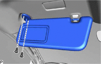
Remove the 2 screws and visor assembly LH.
-
-
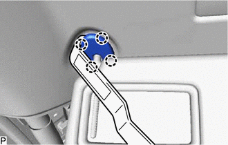
REMOVE VISOR HOLDER (for LH Side)
-
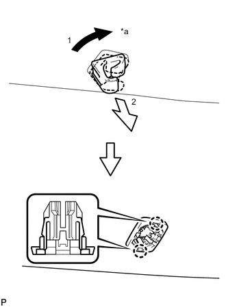
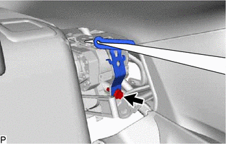
*a 45° Turn the visor holder approximately 45° and pull it out as indicated by the arrows, in the order shown in the illustration.
-
Disengage the 2 claws and remove the visor holder.
-
-
REMOVE ASSIST GRIP SUB-ASSEMBLY (for RH Side)
Tech Tips
Use the same procedure as for the LH side.
-
REMOVE VISOR BRACKET COVER (for RH Side)
Tech Tips
Use the same procedure as for the LH side.
-
REMOVE VISOR ASSEMBLY RH
Tech Tips
Use the same procedure as for the LH side.
-
REMOVE VISOR HOLDER (for RH Side)
Tech Tips
Use the same procedure as for the LH side.
-
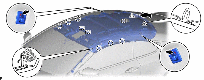
REMOVE ROOF HEADLINING ASSEMBLY
-
for Windshield Glass Side:
-
Disconnect each connector.
-
-
for Front Pillar LH Side:
-
Using a clip remover, disengage the 3 clamps.
-
Disconnect the 2 connectors.
-
-
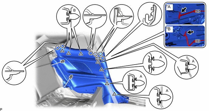
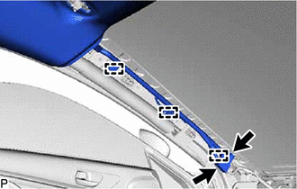
for Roof Side (w/o Sliding Roof):
-
Remove the 2 screws from the 2 coat hooks.
-
Disengage the 6 claws.
-
Slide the roof headlining assembly to disengage the 2 clips and 3 guides as shown in the illustration.
Tech Tips
Leave the 2 clips installed the vehicle body.
-
-
for Roof Side (w/ Sliding Roof):
-
Disconnect the connector from the sliding roof drive gear sub-assembly.
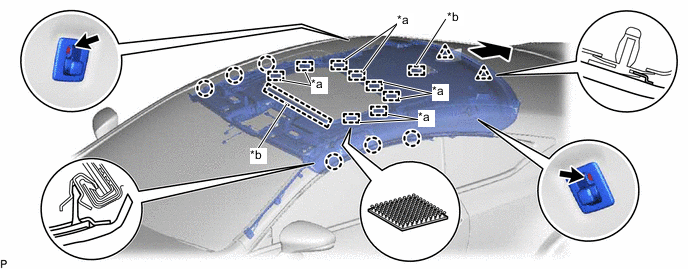
*a Fastener *b Guide -
Remove the 2 screws from the 2 coat hooks.
-
Disengage the 6 claws and 8 fasteners.
-
Slide the roof headlining assembly to disengage the 2 clips and 2 guides as shown in the illustration.
Tech Tips
Leave the 2 clips installed the vehicle body.
-
-
Remove the roof headlining assembly from the vehicle through the front passenger door as shown in the illustration.
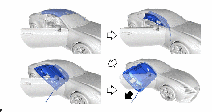
Note
Do not damage the roof headlining assembly or vehicle interior.
-
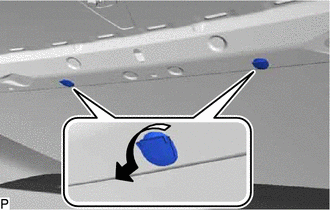
Remove the 2 clips from the vehicle body as shown in the illustration.
-
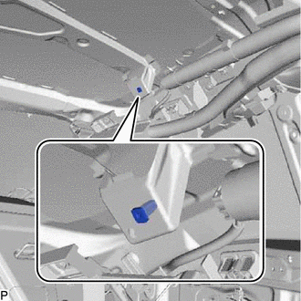
Remove the grommet from the vehicle body.
Tech Tips
Use the same procedure for the RH side and LH side.
-